Getting Started
Your first SOLIDWORKS part, step by step
This tutorial builds a simple mounting plate — 100 × 60 × 20 mm with a Ø20 mm hole and rounded corners — using the four commands you will use in almost every part: Sketch, Smart Dimension, Extruded Boss/Base and Extruded Cut, plus Fillet. It takes about 15 minutes. At the end you check your model against a known mass, the same way certification exams do.
 Kevin Walsh
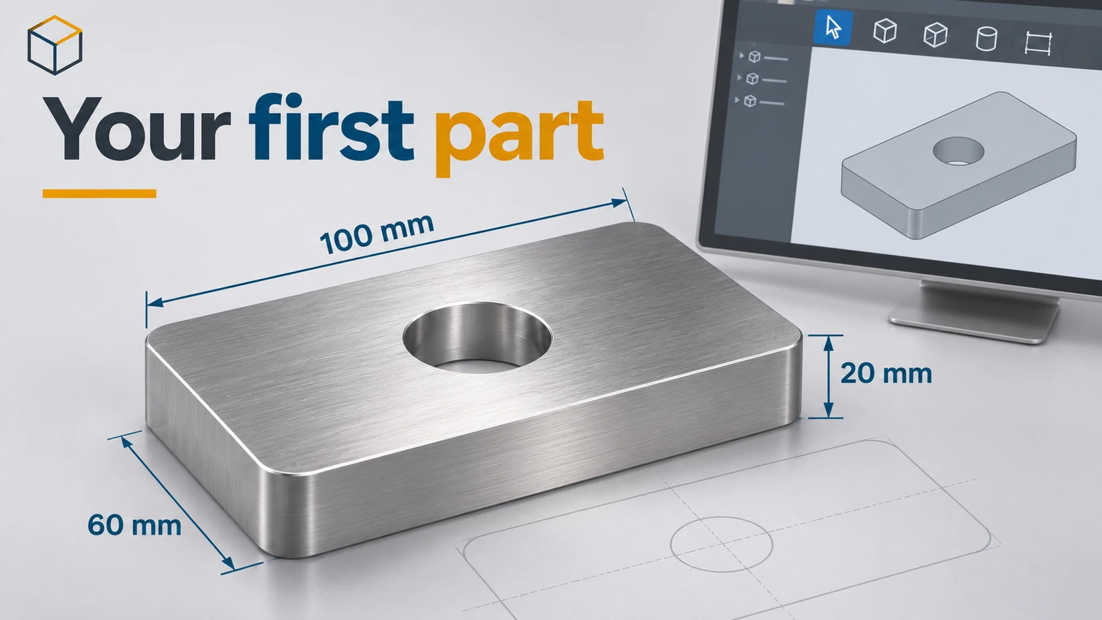
Where to find it
File → New → Part → Sketch tab
What you will build
| Feature | Command | Values |
|---|---|---|
| Plate | Extruded Boss/Base | Centre rectangle 100 × 60 mm, 20 mm deep |
| Hole | Extruded Cut | Ø20 mm, Through All, centred |
| Corners | Fillet | R5 on the four 20 mm edges |
| Material | Edit Material | 6061 aluminium, 2.70 g/cm³ |
| Check | Mass Properties | 305.88 g, 113,287.61 mm³ |
The check values are calculated from the dimensions: 100 × 60 × 20 mm minus the Ø20 hole minus what the four R5 fillets remove. If you know the interface already, you can go straight to the steps.
Ready for more? Model the base plate next, then the other basic exercises.
Step by step
-
1
Create a new part in millimetres
File → New → Part → OK. Look at the bottom right of the window: it should say MMGS. If not, click it and choose MMGS (see units).
-
2
Start a sketch on the Front Plane
In the FeatureManager tree click Front Plane, then on the Sketch tab click Sketch. The view turns to face the plane.
-
3
Draw a centre rectangle on the origin
Choose Rectangle → Center Rectangle. Click on the origin (the red arrows) to place the centre, then click again anywhere to set the corner. Starting on the origin ties the sketch to it.
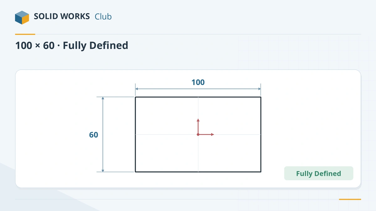
A centre rectangle on the origin, fully defined with two dimensions. -
4
Add dimensions with Smart Dimension
Click Smart Dimension, click the top line and place the dimension; type 100 and press Enter. Click a vertical line and type 60. The lines turn from blue to black, and the status bar says Fully Defined — the sketch can no longer move.
-
5
Extrude it into a solid
On the Features tab click Extruded Boss/Base. Set Direction 1 to Blind and the depth to 20 mm, then click the green tick. You now have a plate.
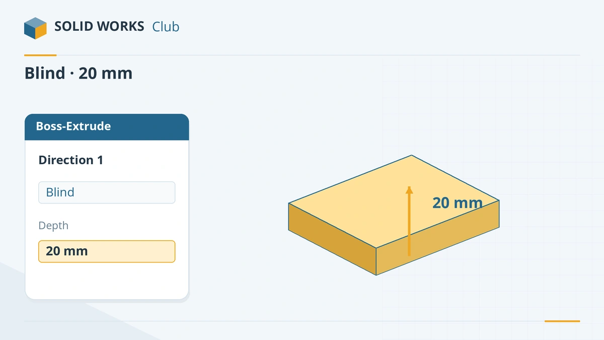
Extruded Boss/Base turns the sketch into a 20 mm thick solid. -
6
Sketch the hole on the front face
Click the large front face of the plate, then Sketch. Draw a Circle with its centre on the origin, and dimension its diameter 20. The circle turns black.
-
7
Cut the hole through
Features → Extruded Cut, end condition Through All, tick. The hole goes through the plate.
-
8
Round the four corners
Features → Fillet, radius 5 mm. Select the four short edges at the corners of the plate (the edges 20 mm long), then the tick. Fillets come last in most parts — they are easy to change and do not break the features before them.
-
9
Add material and check the mass
Right-click Material in the tree → Edit Material, choose the 6061 alloy in the aluminium group of the SOLIDWORKS materials and check that its density reads 2,700 kg/m³ (2.70 g/cm³) → Apply. Then Evaluate → Mass Properties. The mass should be about 305.88 g (volume 113,287.61 mm³). A different value means a dimension or the fillet selection is off.
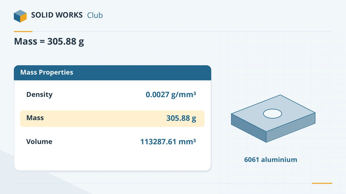
Your mass should be about 305.88 g with 6061 aluminium. -
10
Save the part
File → Save As, name it
mounting-plate.SLDPRT. Rename the features in the tree (slow double-click) — Plate, Hole, Corner fillets — so they are easy to find later.
Common mistakes
- Starting the rectangle away from the origin. The sketch then needs extra dimensions to be fully defined.
- Leaving sketches blue (under defined). They can change shape when you edit something else.
- Filleting the 100 mm or 60 mm edges instead of the four 20 mm corner edges — the mass will not match.
- Working in inches by mistake — 100 would become 100 inches. Check MMGS in the status bar first.
What to do next
- Do the built-in Lesson 1 – Parts tutorial (Welcome dialog → Learn), which adds a boss, a cut, fillets and a shell.
- Follow the learning plan for assemblies and drawings.
- Learn each sketch tool properly in the sketching course.
- Learn every feature used here — and many more — in the features course.
- Save your projects in a clean folder structure from the start.
- When you can model simple parts confidently, try the CSWA practice test — its modelling questions are checked by mass, just like this part.
- Sketch turning red or the extrude failing? See sketch errors.
Sources
- 3DEXPERIENCE community — Creating your first part (Jun 2026)
- GoEngineer — Mastering basic part modeling (Jul 2025)
- GoEngineer — Getting started: Lesson 1 Parts (built-in tutorials)
- CADimensions — Sketch troubleshooting guide
- Solid Solutions — How to change units in SOLIDWORKS (Jul 2023)
Checked November 2026. SOLID WORKS Club is independent; menu names can differ slightly between releases.
Frequently asked questions
What is the first thing to learn in SOLIDWORKS?
+
Sketching on a plane, adding dimensions until the sketch is fully defined, and turning it into a solid with Extruded Boss/Base. Almost every part starts that way.
Why are my sketch lines blue?
+
Blue means the sketch is under defined — it can still move. Add dimensions or relations until the lines turn black and the status bar says Fully Defined.
Which plane should I sketch on first?
+
The one that matches how the part is viewed from the front. For a plate seen from the front, the Front Plane; for a part that sits on a table, often the Top Plane.
How long does it take to learn SOLIDWORKS basics?
+
Most people can build simple parts after a few hours with the built-in tutorials. A structured course for parts, assemblies and drawings usually takes several days; see our learning plan.
Related
- The SOLIDWORKS interface explainedA beginner's map of the SOLIDWORKS interface — CommandManager, FeatureManager tree, PropertyManager, Task Pane, heads-up toolbar, status bar and the S key.
- How to learn SOLIDWORKS — a 30-day planA practical 30-day plan to learn SOLIDWORKS for free — built-in tutorials, free MySolidWorks training, official videos, practice parts and the CSWA as a goal.
- Free CSWA practice testFree CSWA-style practice test with a 45-minute timer — knowledge questions plus five modelling problems with drawings, scored with worked answers.
- SOLIDWORKS sketch errors — over defined, unsolvable and open sketchesFix SOLIDWORKS sketch errors: over defined, no solution found, dangling relations, open or self-intersecting contours, with SketchXpert and Repair Sketch.