Sketching · Lesson 11
Construction geometry and centerlines
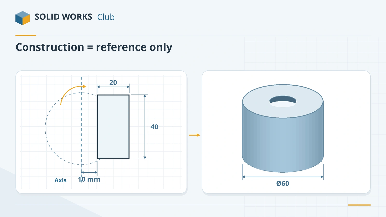
Construction geometry is sketch geometry that helps you draw but does not become part of the solid. It appears as dashed lines. Use it for mirror lines, revolve axes, symmetry, reference circles for bolt holes and helper lines for dimensions. Any sketch entity can be switched to construction and back; Centerline draws a construction line directly.
 Kevin Walsh
Where to find it
Sketch tab → Line flyout → Centerline; or select entities → Construction Geometry (context toolbar)
Where construction geometry helps
| Use | Construction entity |
|---|---|
| Revolve axis | Centerline |
| Mirror line | Centerline — see Mirror Entities |
| Symmetry | Centerline with Symmetric relations |
| Bolt circle | Construction circle with holes on it — see sketch patterns |
| Polygon size | The polygon's own construction circle |
| Rectangle centre | Rectangle option Add construction lines |
| Angled dimension references | Construction line at the angle |
Since SOLIDWORKS 2024 SP1, Convert Entities can also create its result directly as construction geometry — useful for referencing model edges without building on them; see Convert Entities.
Step by step
-
1
Draw a centerline as the axis
On the Front Plane, Line → Centerline: draw a vertical centerline starting at the origin.
-
2
Sketch the profile beside it
Draw a Corner Rectangle to the right of the centerline: 20 mm wide, 40 mm tall, with its left side 10 mm from the centerline and its bottom on the horizontal through the origin.
-
3
Revolve
Features → Revolved Boss/Base. With a single centerline in the sketch, SOLIDWORKS picks it as the axis automatically. Keep 360° and click the tick — you get a tube.
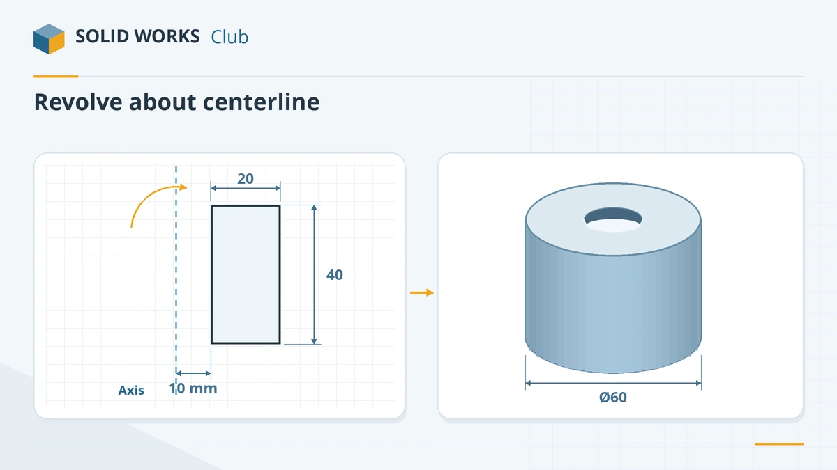
The centerline becomes the revolve axis; the rectangle becomes the tube wall. -
4
Convert existing entities
To turn a normal line into construction, select it and click Construction Geometry in the context toolbar, or tick For construction in its PropertyManager. Do the same to turn it back.
Common mistakes
- Using a normal line as the revolve axis inside a profile — the profile then has an extra line and the revolve may fail. Use a centerline.
- Letting the profile cross the revolve axis — the revolve fails.
- Construction circles for bolt patterns drawn as normal circles — they then cut an extra groove. Switch them to construction.
Lesson 11 of 17 in the sketching course.
Practice
Build the tube above: a 20 × 40 mm rectangle 10 mm away from a vertical centerline, revolved 360°. Check: volume 100,530.96 mm³ (inner Ø20, outer Ø60, 40 mm tall).
Sources
- SOLIDWORKS Help 2024 — Converting sketch entities to construction geometry
- Solid Solutions — How to create a revolve (Jul 2023)
- GoEngineer — Mirror Entities and Dynamic Mirror
- CATI — Rectangle construction lines
- Planchard — SOLIDWORKS 2020 Reference Guide, sketch chapter (sample PDF)
Checked November 2026. SOLID WORKS Club is independent; menu names can differ slightly between releases.
Frequently asked questions
What is construction geometry in SOLIDWORKS?
+
Sketch geometry shown as dashed lines that is used for reference — axes, mirror lines, helper lines — and is ignored when SOLIDWORKS builds the feature.
How do I make a line a construction line?
+
Select it and click Construction Geometry in the context toolbar, or tick For construction in the line's PropertyManager. Right-click and Tools → Sketch Tools → Construction Geometry also work.
What is the difference between a centerline and a construction line?
+
None in practice — a centerline is a line drawn as construction geometry from the start.
Which axis does a revolve use?
+
A centerline, an axis, a sketch line or a linear edge. If the sketch has exactly one centerline, SOLIDWORKS uses it automatically.
Related
- Mirror sketch entities in SOLIDWORKSHow to mirror sketch geometry in SOLIDWORKS with Mirror Entities and Dynamic Mirror, choose a centerline, line, edge or plane, and keep the halves symmetric.
- SOLIDWORKS Line toolHow to draw lines in SOLIDWORKS: the Line, Centerline and Midpoint Line tools, chain drawing, switching to a tangent arc, orientation options and L.
- Linear and circular sketch patternsHow to use linear and circular sketch patterns in SOLIDWORKS: spacing, instances, angle, editing a pattern, and when a feature pattern is the faster choice.
- SOLIDWORKS rectangle toolsHow to sketch rectangles in SOLIDWORKS: Corner, Center, 3 Point Corner, 3 Point Center and Parallelogram, with construction lines and centring.