Sheet metal · Lesson 13
Export a flat pattern to DXF for laser cutting
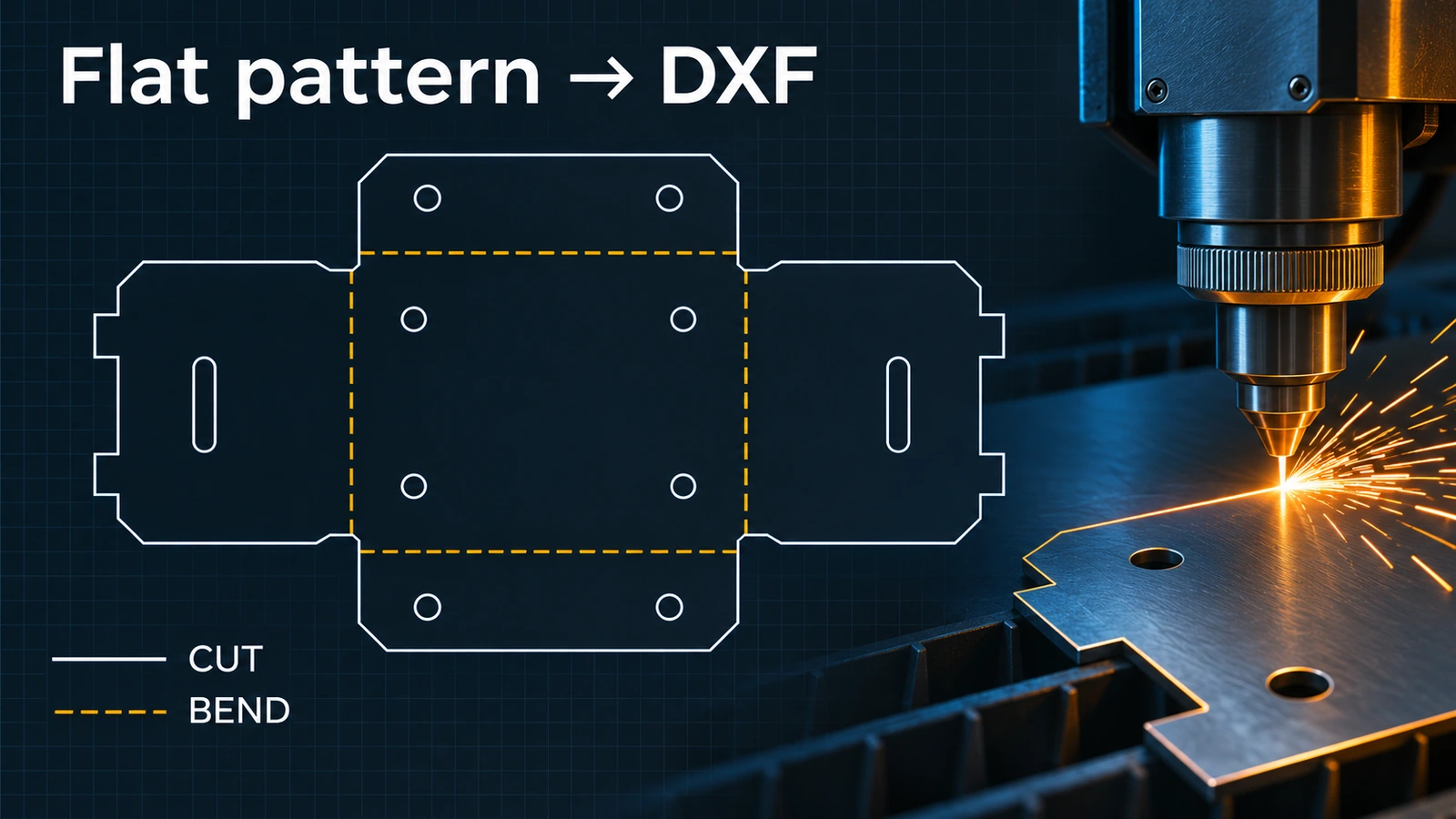
Laser and plasma shops want a DXF of the flat blank — just the cut outline, at 1:1, without dimensions or title blocks. SOLIDWORKS exports it straight from the part with Export to DXF/DWG: choose Sheet metal, pick what to include, align the output, clean up stray lines in the preview and save. Map bend lines to their own layer so they are not cut.
 Kevin Walsh
Where to find it
Right-click a flat face or Flat-Pattern → Export to DXF/DWG; File → Save As → DXF
What to include
| Entity | For the laser? |
|---|---|
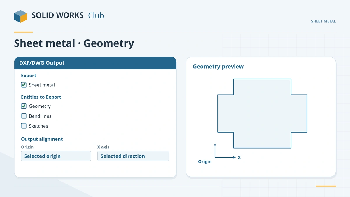
| Geometry | Yes — the cut outline and holes (default) |
| Bend lines | Only on their own layer, if the shop wants them |
| Sketches | For etch or marking lines |
| Bounding box | Rarely — it is not a cut |
Export options: a single file holds everything selected; separate files writes one per selection. Check the result in eDrawings or DraftSight before sending. Drawing exports and DXF scale settings are covered in export to PDF, DXF and DWG; other part conversions in convert to DXF. This is the last lesson of the sheet metal course.
Practise it: export the blank of the sheet metal box and the plate of the drone frame.
Step by step
-
1
Start the export
In the bracket, right-click the Flat-Pattern feature (or a flat face) → Export to DXF/DWG, choose a file name.
-
2
Choose what to export
Under Export choose Sheet metal. Under entities keep Geometry; add Bend lines only if the shop wants them, and Sketches for etch marks.
Choose Sheet metal and keep only the entities the shop needs. -
3
Align and clean up
Optionally pick a vertex as the origin and an edge as the X axis. Click the tick; in the DXF/DWG Cleanup preview, select any line you do not want cut and use Remove Entities, then Save.
-
4
Map layers
For repeat work, set up a map file (Tools → Options → Export → DXF/DWG, custom map): geometry on CUT, sketches on ETCH, bend lines on BEND-UP and BEND-DOWN with a centreline linetype.
Common mistakes
- Bend lines on the same layer as the cut — the laser cuts them. Since 2022 there is no default bend layer; map one.
- Exporting from a drawing sheet with dimensions, notes and a title block — they become cut geometry.
- Wrong size at the shop — DXF has no units. Model at 1:1 and tell the shop mm or inches.
- Splines the machine cannot read — switch the spline export setting to polylines in the DXF/DWG export options.
Lesson 13 of 13 in the sheet metal course.
Practice
Export the bracket's flat pattern to DXF with geometry only. Check: in eDrawings or a free DXF viewer the outline measures 100 × 86.71 (mm), with no bend lines and no extra entities.
Sources
- CATI — Save sheet metal parts directly to DXF or DWG (Jan 2008)
- SOLIDWORKS Blog — Creating DXF files (May 2012)
- GoEngineer — Export flat pattern to DXF (Jul 2024)
- Hawk Ridge — DXF/DWG export
- SOLIDWORKS Help 2024 — DXF/DWG Output PropertyManager
- TriMech — DXF and DWG exporting from part files
- Javelin — Exporting SOLIDWORKS model data to DXF/DWG (Oct 2025)
- Visiativ UK — Use a DXF mapping file with sheet metal (Jun 2025)
- SendCutSend — Map bend lines into layers and linetypes (Nov 2022)
Checked November 2026. SOLID WORKS Club is independent; menu names can differ slightly between releases.
Frequently asked questions
How do I export a sheet metal flat pattern to DXF?
+
Right-click the Flat-Pattern feature or a flat face, choose Export to DXF/DWG, select Sheet metal, pick the entities and save after the cleanup preview.
Should I include bend lines in the DXF?
+
Only if the shop asks. Put them on a separate layer with a centreline linetype so they are not cut.
Why is my DXF the wrong size?
+
DXF files are unitless. Export at 1:1 from the part and tell the shop the units you modelled in.
Since when can SOLIDWORKS export flat patterns directly?
+
Since SOLIDWORKS 2008. Before that it needed a macro.
Related
- How to export DXF and DWG from SOLIDWORKSHow to export SOLIDWORKS drawings to DXF or DWG for AutoCAD, and sheet metal flat patterns to DXF for laser cutting — options, bend lines and common problems.
- Export drawings to PDF, DXF and DWGExport SOLIDWORKS drawings to PDF, DXF and DWG: Save As PDF vs printing, high-quality lines, DXF/DWG options, true 1:1 scale and flat patterns.
- Flat patterns in SOLIDWORKS sheet metalHow the SOLIDWORKS flat pattern works: Flatten, Flat-Pattern options, Unfold and Fold for cuts across bends, bend lines and flat drawing views.
- eDrawings: the free SOLIDWORKS file viewerWhat eDrawings is, how to get the free Viewer for Windows, Mac, iPhone and Android, what it opens, what Professional adds and how to publish eDrawings files.