Project 9
How to design a drone frame in SOLIDWORKS
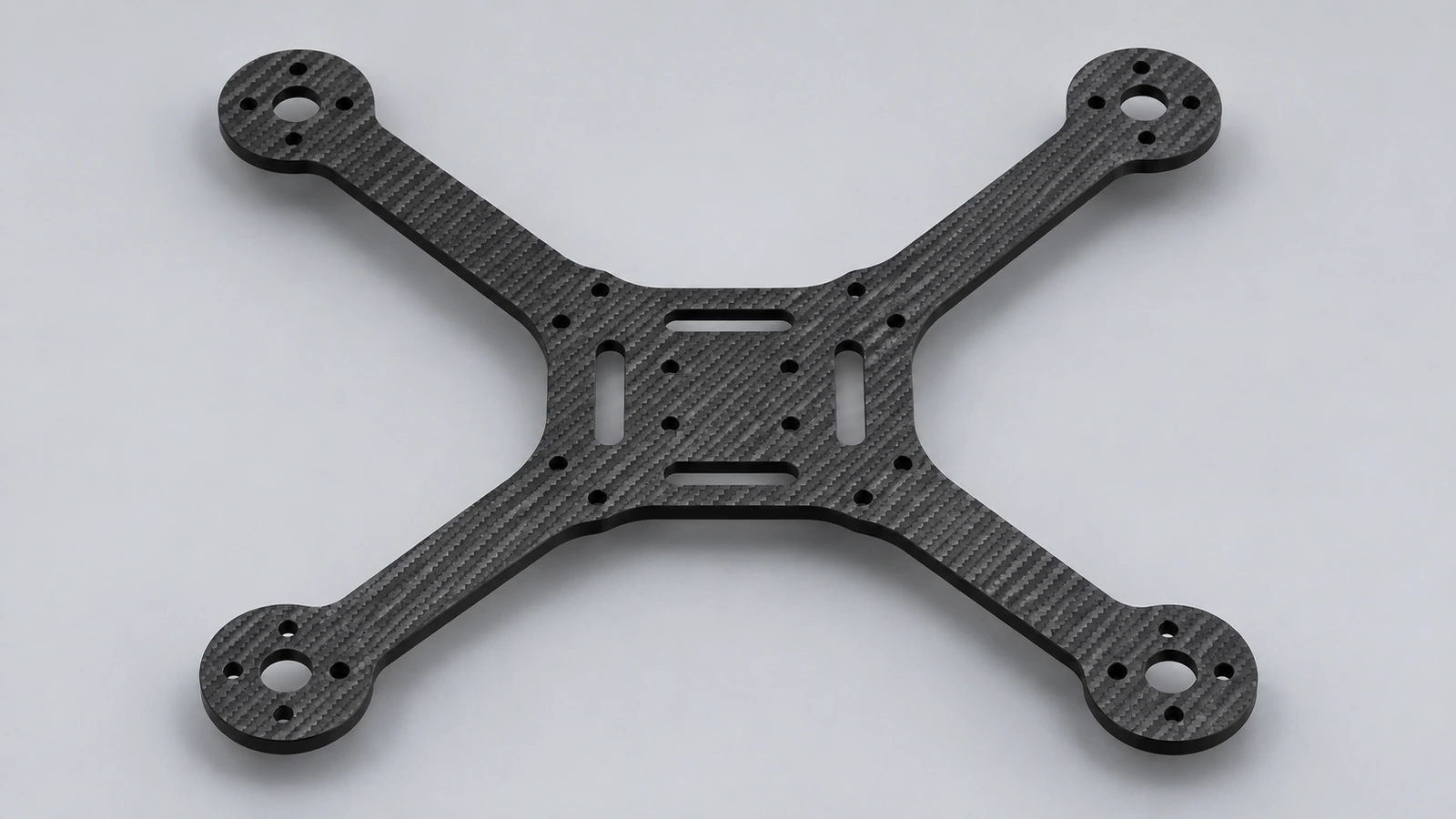
FPV frames are flat plates cut from carbon sheet, which makes them ideal for a sketch-driven SOLIDWORKS project. The size class is the diagonal motor-to-motor distance — 250 mm here — and the hole patterns come from the components: 16 × 19 mm M3 for many 22xx motors and 30.5 × 30.5 mm M3 for a standard flight controller stack.
 Kevin Walsh
- Level
- Project
- Time
- 45 min
- Material
- Carbon sheet or aluminium, 4 mm
Specification
| Parameter | Value |
|---|---|
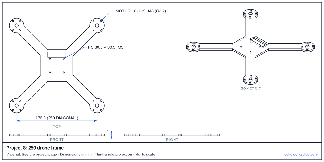
| Wheelbase (motor diagonal) | 250 mm |
| Motor centres | 176.8 × 176.8 mm square |
| Motor holes | 16 × 19 mm, M3 (Ø3.2) |
| Flight controller | 30.5 × 30.5 mm, M3 |
| Plate | 4 mm (arm thickness used on 250-class frames) |
The drawing
Step by step
1. Layout
Sketch construction lines at 45° from the origin to the motor centres, 125 mm out — giving the 250 mm diagonal.
2. Outline
Centre plate 70 × 70 with R10 corners, 20 mm wide arms, Ø32 motor pads. Fillet the arm roots.
3. Holes
Motor pattern 16 × 19 with Ø3.2 holes and a centre clearance hole; FC 30.5 × 30.5 with Ø3.2; a slot for wiring.
4. Extrude and mirror
Extrude 4 mm; draw one arm and use Circular Pattern or Mirror for the others.
5. Export for cutting
Save the face as DXF at 1:1 for waterjet or CNC routing.
Check your result
- Motor-to-motor diagonal 250 mm.
- Plate volume 50,097.39 mm³ — multiply by your sheet's density for the mass.
Compare your model with the STEP file above — it opens in SOLIDWORKS and most other CAD programs.
Next: project 10 — bench vise.
Download files
Commands used
Show solution
- Layout. Sketch construction lines at 45° from the origin to the motor centres, 125 mm out — giving the 250 mm diagonal.
- Outline. Centre plate 70 × 70 with R10 corners, 20 mm wide arms, Ø32 motor pads. Fillet the arm roots.
- Holes. Motor pattern 16 × 19 with Ø3.2 holes and a centre clearance hole; FC 30.5 × 30.5 with Ø3.2; a slot for wiring.
- Extrude and mirror. Extrude 4 mm; draw one arm and use Circular Pattern or Mirror for the others.
- Export for cutting. Save the face as DXF at 1:1 for waterjet or CNC routing.
Sources
- The Drone Flight — FPV component compatibility guide (Nov 2025)
- Unmanned Tech Shop — FPV motor mounting and screw length (Apr 2026)
- IntoFPV forum — 22xx motor mounting patterns
- Racer.lt — Motor mount for 2204/2206, 16/19 mm holes
- Evelta — ZMR250 / QAV250 frame, 4 mm arms
- Oscar Liang — C250 mini quad frame review (Aug 2014)
- GetFPV — SpeedyBee 5-inch freestyle frame
- Rotorama — 20×20 / 30.5×30.5 stack adapter
Checked November 2026. SOLID WORKS Club is independent; menu names can differ slightly between releases.
Frequently asked questions
What does 250 mean in a drone frame?
+
The diagonal distance between motor centres, in millimetres.
Which motor hole pattern should I use?
+
Check your motor: 16 × 19 mm and 16 × 16 mm with M3 screws are common for 22xx motors; smaller frames use 9 × 9 or 12 × 12 mm with M2.
Related
- How to model a bench vise in SOLIDWORKSModel a bench vise assembly in SOLIDWORKS: body, moving jaw, lead screw and handle, a screw mate for travel and a limit distance mate for the opening.
- How to design a phone case in SOLIDWORKSDesign a phone case in SOLIDWORKS around a phone body: 0.3 mm clearance, 1.5 mm walls, a 1 mm screen lip and a camera opening, sized for TPU 3D printing.
- Construction geometry and centerlinesHow construction geometry works in SOLIDWORKS: centerlines, For construction, converting entities, and using them as mirror lines, revolve axes and references.
- Intermediate SOLIDWORKS exercises19 intermediate SOLIDWORKS exercises: sweeps, lofts, shells, draft, Hole Wizard and three small assemblies, each with a drawing, STEP file and check mass.