Features · Lesson 10
SOLIDWORKS Draft
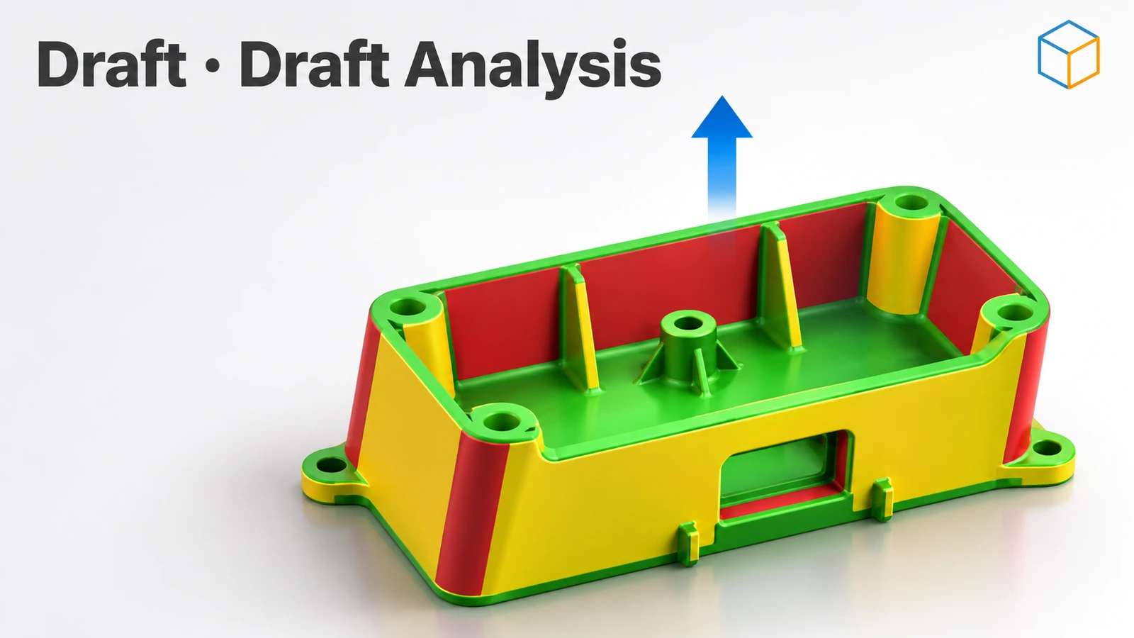
Draft tilts faces by a small angle so a moulded or cast part can be pulled out of its mould. Without draft, vertical walls scrape against the tool or stick. The Draft feature adds it to existing faces; Extrude, Cut and Rib also have a draft option of their own. Draft Analysis colours the model so you can see which faces still need it.
 Kevin Walsh
Where to find it
Features tab → Draft; Evaluate tab → Draft Analysis
Draft types
| Type | Pivots about | Use |
|---|---|---|
| Neutral Plane | A plane or face | Most parts; walls tilt from one reference |
| Parting Line | An edge, usually a split line | Different draft on each side of the parting line (no cylindrical faces) |
| Step Draft | A parting line, with a step | Parts that need a step at the parting line |
| DraftXpert | Neutral plane only | Adds and changes drafts quickly, with analysis built in |
Draft Analysis colours
| Colour | Meaning |
|---|---|
| Green | Positive draft — releases in the pull direction |
| Red | Negative draft — releases the other way |
| Yellow | Needs draft (below the angle you set) |
The tool's default analysis angle in Mold Tools is 3°. Ribs need draft too — see Rib. To simulate how a moulded part fills, see SOLIDWORKS Plastics.
Practise it: the drafted tray exercise.
Step by step
-
1
Build the block
Extrude a 60 × 40 mm Center Rectangle on the Top Plane 30 mm up.
-
2
Start a Neutral Plane draft
Features → Draft, type Neutral Plane, angle 5°. As the Neutral Plane pick the bottom face — it stays the same size and the walls pivot about it.
-
3
Pick the faces to draft
Select the four side faces. Check the preview: the top should get smaller. If it gets bigger, click the arrow next to the neutral plane to reverse the pull direction.
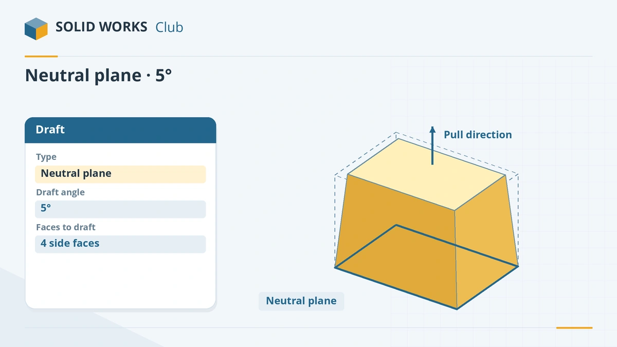
The bottom face stays the same; the side walls tilt inward by 5°. -
4
Check with Draft Analysis
Evaluate → Draft Analysis, pull direction = bottom face, angle 1°. Green faces have positive draft, red negative, yellow need draft. All four sides should now be coloured as drafted.
Common mistakes
- Drafting the wrong way — the part gets wider towards the parting line. Reverse the direction.
- Too little draft on textured faces. SOLIDWORKS' moulding advice is at least 1° on vertical faces plus about 1° per 0.001 in (0.025 mm) of texture depth.
- Adding draft after small fillets. Add large corner fillets before draft and small fillets after.
Lesson 10 of 18 in the features course.
Practice
Draft the four sides of a 60 × 40 × 30 mm block by 5° about the bottom face, inward. Check: volume 64,401.57 mm³; the top face becomes about 54.75 × 34.75 mm.
Sources
- Hawk Ridge — Draft features you need to know (Aug 2022)
- TriMech — How to design with the Draft feature
- GoEngineer — Mold Tools: Draft Analysis (Nov 2021)
- Javelin — Quick face selection with DraftXpert
- SOLIDWORKS Tech Blog — Top five injection molded part design errors (2019)
- SOLIDWORKS blog — Cardinal rules of designing injection molded parts
- Javelin — How feature ordering affects your design (Jun 2026)
Checked November 2026. SOLID WORKS Club is independent; menu names can differ slightly between releases.
Frequently asked questions
How much draft do I need?
+
At least 1° on vertical faces for most moulded parts, more for tall walls and textured surfaces. Ask your mould maker — material and texture change the answer.
What is the difference between Neutral Plane and Parting Line draft?
+
Neutral Plane draft pivots faces about a plane or face. Parting Line draft pivots about an edge, usually a split line, so each side of the parting line can have its own draft.
How do I check draft in SOLIDWORKS?
+
Use Draft Analysis on the Evaluate tab. Set the pull direction and the required angle; faces turn green, red or yellow.
Can I add draft while extruding?
+
Yes. Extruded Boss, Extruded Cut and Rib have a Draft option that tapers the walls as they are created.
Related
- SOLIDWORKS RibHow to use the Rib feature in SOLIDWORKS: one open sketch line, thickness, parallel or normal direction, draft, and rib design rules for plastic parts.
- SOLIDWORKS ShellHow to use Shell in SOLIDWORKS to hollow a part: faces to remove, wall thickness, shell outward, multi-thickness walls, and what to do when the shell fails.
- SOLIDWORKS Extruded Boss/BaseHow to use Extruded Boss/Base in SOLIDWORKS: every end condition from Blind to Mid Plane, Direction 2, draft, thin features, Selected Contours and Merge result.
- SOLIDWORKS FilletHow to use Fillet in SOLIDWORKS: constant, variable, face and full round fillets, profiles, tangent propagation, FilletXpert and why fillets fail.