Features · Lesson 1
SOLIDWORKS Extruded Boss/Base
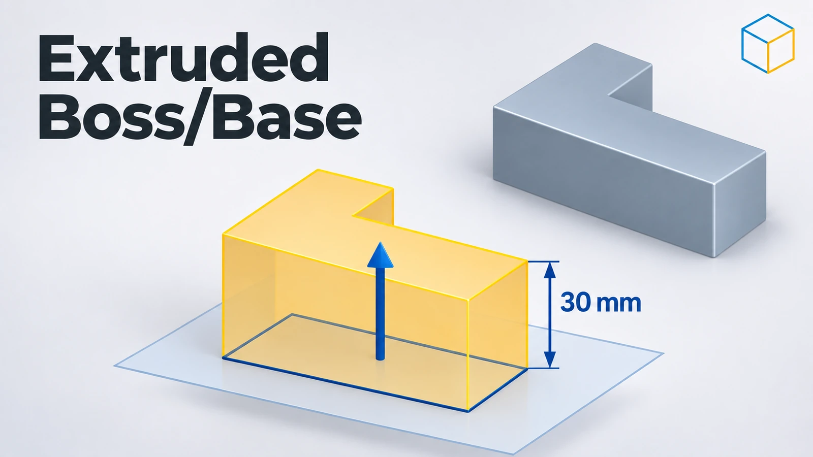
Extruded Boss/Base pushes a 2D sketch straight out into a solid. It is the first feature of most parts. You choose where it starts (From), how far it goes (the end condition — a set depth, up to a face, through everything), and optionally a second direction, a draft angle or a thin wall. A closed sketch makes a solid; an open sketch makes a thin-walled feature.
 Kevin Walsh
Where to find it
Features tab → Extruded Boss/Base (Insert → Boss/Base → Extrude)
End conditions
| End condition | Extrudes… |
|---|---|
| Blind | A set distance from the sketch plane |
| Through All | Through all existing geometry |
| Through All – Both | Through everything in both directions |
| Up To Next | To the next surface that blocks the whole profile |
| Up To Vertex | To a plane through a chosen vertex, parallel to the sketch |
| Up To Surface | To a chosen face or plane |
| Offset From Surface | To a set distance from a chosen face |
| Up To Body | Up to a chosen body |
| Mid Plane | Equally to both sides of the sketch plane |
From the official SOLIDWORKS Help list of extrude end conditions.
Other options in the PropertyManager
| Option | What it does |
|---|---|
| From | Start at the sketch plane (default), an offset, a vertex or another face or plane — no extra plane needed |
| Direction 2 | A second, independent extrusion the other way |
| Draft | Tapers the sides by an angle, for moulded and cast parts |
| Thin Feature | Gives the profile a wall thickness — one direction, two directions or mid-plane |
| Selected Contours | Extrude only some regions of the sketch |
| Merge result | Joins the new solid to the existing body (on by default) |
| Feature Scope | Chooses which bodies the feature affects in multibody parts |
Next: remove material with Extruded Cut.
Step by step
-
1
Sketch the profile
On the Front Plane sketch a Circle Ø40 centred on the origin and fully define it.
-
2
Start the extrude
With the sketch selected (or still open), click Features → Extruded Boss/Base. A yellow preview and a drag arrow appear.
-
3
Choose Mid Plane
In Direction 1 change Blind to Mid Plane and type 30 mm. The cylinder now grows 15 mm to each side of the Front Plane, so the part stays symmetric about it.
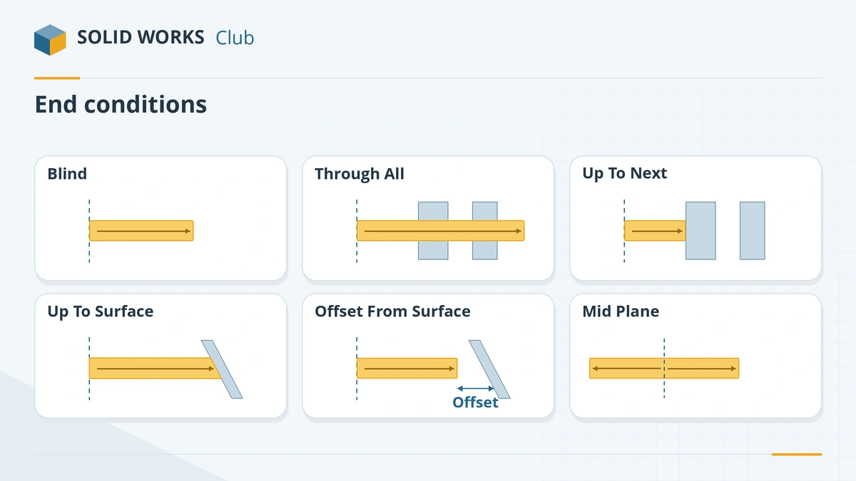
How the main end conditions decide where the extrude stops. -
4
Confirm
Click the green tick. You can also set the depth by dragging the arrow (Instant3D) — a ruler appears for exact values.
Common mistakes
- Using Blind in one direction for a symmetric part. Mid Plane keeps it centred on the sketch plane, which helps mirroring and mating later.
- Leaving a tiny gap in the sketch. An open profile turns the extrude into a thin feature, which is rarely what beginners want.
- Up To Next when the next face does not cover the whole profile — it then fails. Use Up To Surface instead.
- Unticking Merge result by accident, which leaves a separate body in the part.
Lesson 1 of 18 in the features course.
Practice
Extrude a Ø40 circle on the Front Plane with Mid Plane, 30 mm. Check: volume 37,699.11 mm³, and the Front Plane cuts the cylinder exactly in half.
Sources
- SOLIDWORKS Help 2024 — Creating an extrude feature
- SOLIDWORKS Help 2024 — End conditions for extrudes
- TriMech — Extrude options in SOLIDWORKS
- CADimensions — Do you really know the Extrude feature?
- CATI — Thin features from open contours
- TriMech — Using Selected Contours
- Javelin — Multibody parts and Merge result (Jul 2026)
- Hawk Ridge — Feature Scope in SOLIDWORKS (Dec 2023)
- Hawk Ridge — Draft features you need to know (Aug 2022)
- SOLIDWORKS Tech Blog — Instant2D and Instant3D (2020)
Checked November 2026. SOLID WORKS Club is independent; menu names can differ slightly between releases.
Frequently asked questions
What is the difference between Blind and Mid Plane?
+
Blind extrudes the set distance in one direction from the sketch plane. Mid Plane extrudes the total distance split equally on both sides.
What does Up To Next do?
+
It extrudes up to the next surface that blocks the entire profile in the same part. If no single surface blocks the whole profile, use Up To Surface.
Can I extrude an open sketch?
+
Yes, as a thin feature: SOLIDWORKS adds a wall thickness to the open profile. You can also tick Thin Feature with a closed profile to get a hollow shape.
How do I extrude only part of a sketch?
+
Use Selected Contours in the PropertyManager and pick the regions or contours to extrude. One sketch can then drive several features.
Related
- SOLIDWORKS Extruded CutHow to use Extruded Cut in SOLIDWORKS: sketch on a face, choose Blind or Through All, flip side to cut, open-profile cuts, and when to use Hole Wizard.
- SOLIDWORKS RevolveHow to use Revolved Boss/Base and Revolved Cut in SOLIDWORKS: sketch half a profile, choose the axis, set the angle and fix open-sketch errors.
- SOLIDWORKS sketching — basics and all toolsLearn SOLIDWORKS sketching from scratch: start and exit a sketch, read colours and status, then 17 lessons from lines and arcs to relations and 3D sketches.
- Your first SOLIDWORKS part, step by stepModel your first SOLIDWORKS part in 15 minutes: a sketch on the Front Plane, Smart Dimension, Extruded Boss, a hole and fillets, with a check mass.