Project 2
How to make a helical gear in SOLIDWORKS
A helical gear is a spur gear whose teeth are twisted along the face width. The twist makes it quieter but changes the geometry: the module and pressure angle are given in the normal plane, while the profile you sketch lies in the transverse plane. Get that conversion right and the rest is a spur gear with a sweep or twisted extrude.
 Kevin Walsh
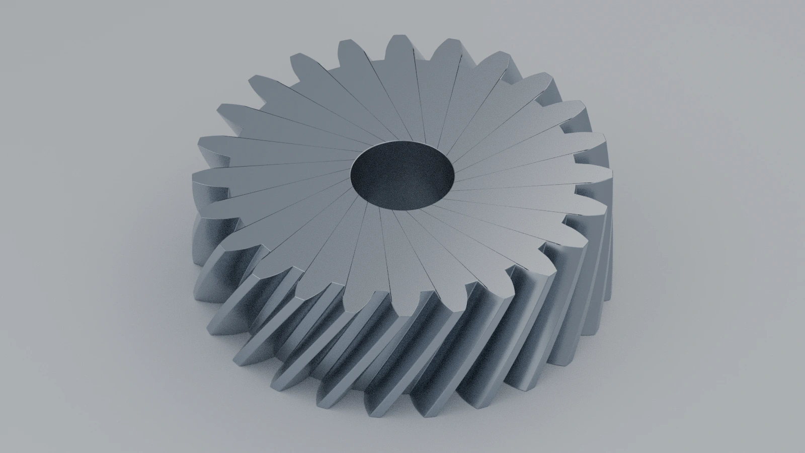
- Level
- Project
- Time
- 45 min
- Material
- Mild steel, 7.85 g/cm³
- Check mass
- 214.97 g
Specification
| Parameter | Value |
|---|---|
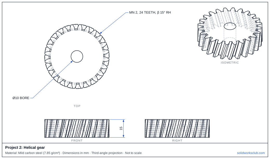
| Normal module mn | 2 mm |
| Teeth z | 24 |
| Helix angle β | 15°, right hand |
| Transverse module mn / cos β | 2.071 mm |
| Pitch diameter mn·z / cos β | 49.69 mm |
| Tip diameter d + 2mn | 53.69 mm |
| Transverse pressure angle atan(tan 20° / cos β) | 20.65° |
| Face width / twist | 15 mm / 9.27° |
The drawing
Step by step
1. Convert to the transverse plane
Compute the transverse module and pressure angle from the normal values: mt = mn / cos β and αt = atan(tan αn / cos β).
2. Sketch the transverse profile
Build one tooth as in the spur gear project, but with mt = 2.071 and αt = 20.65°: pitch Ø49.69, tip Ø53.69.
3. Twist the tooth along the face
Over a 15 mm face width the tooth rotates by 15·tan β / r = 9.27°. Sweep the tooth profile along a helix with that lead, or extrude with a twist.
4. Pattern and bore
Circular-pattern the tooth 24 times, cut the Ø10 bore. Check the hand: a right-hand helix leans to the right when the gear axis is vertical.
5. Toolbox alternative
The ISO Power Transmission → Gears folder also contains a helical gear for assemblies and BOMs.
Check your result
- Measure the tip diameter: Ø53.69.
- Both faces show the same tooth profile, rotated 9.27° relative to each other.
- Our STEP model weighs 214.97 g in mild steel at 7.85 g/cm³.
Compare your model with the STEP file above — it opens in SOLIDWORKS and most other CAD programs.
Next: project 3 — compression spring with closed and ground ends.
Download files
Commands used
Show solution
- Convert to the transverse plane. Compute the transverse module and pressure angle from the normal values: mt = mn / cos β and αt = atan(tan αn / cos β).
- Sketch the transverse profile. Build one tooth as in the spur gear project, but with mt = 2.071 and αt = 20.65°: pitch Ø49.69, tip Ø53.69.
- Twist the tooth along the face. Over a 15 mm face width the tooth rotates by 15·tan β / r = 9.27°. Sweep the tooth profile along a helix with that lead, or extrude with a twist.
- Pattern and bore. Circular-pattern the tooth 24 times, cut the Ø10 bore. Check the hand: a right-hand helix leans to the right when the gear axis is vertical.
- Toolbox alternative. The ISO Power Transmission → Gears folder also contains a helical gear for assemblies and BOMs.
Sources
- Drivetrain Hub — Gear geometry, chapter 3: helical gears
- Engineers Edge — Helical gear calculator
- lucidar.me — Insert gears in a SolidWorks assembly (Apr 2019)
- KHK USA — Standards in terminology for gearing (PDF)
- GoEngineer — How to make a helix in SOLIDWORKS (Jul 2018)
- Hawk Ridge — Is the Toolbox spur gear a good fit? (Jul 2024)
Checked November 2026. SOLID WORKS Club is independent; menu names can differ slightly between releases.
Frequently asked questions
Why is a helical gear's pitch diameter larger than a spur gear's?
+
Because d = mn·z / cos β. With the same normal module and teeth, the helix angle makes the transverse module and pitch diameter larger.
Do two meshing helical gears have the same hand?
+
On parallel shafts they have opposite hands: one right-hand, one left-hand, with the same helix angle.
Related
- How to model a compression spring in SOLIDWORKSModel a real compression spring in SOLIDWORKS: variable-pitch helix for closed ends, sweep, ground ends cut with a plane, and checks for free and solid length.
- How to make a spur gear in SOLIDWORKSModel a module 2, 24-tooth spur gear in SOLIDWORKS two ways: Toolbox for assemblies and a true involute for manufacturing, with checks.
- SOLIDWORKS SweepHow to use Swept Boss/Base and Swept Cut in SOLIDWORKS: profile and path rules, Pierce, circular profiles, orientation, twist and guide curves.
- Intermediate SOLIDWORKS exercises19 intermediate SOLIDWORKS exercises: sweeps, lofts, shells, draft, Hole Wizard and three small assemblies, each with a drawing, STEP file and check mass.