Project 3
How to model a compression spring in SOLIDWORKS
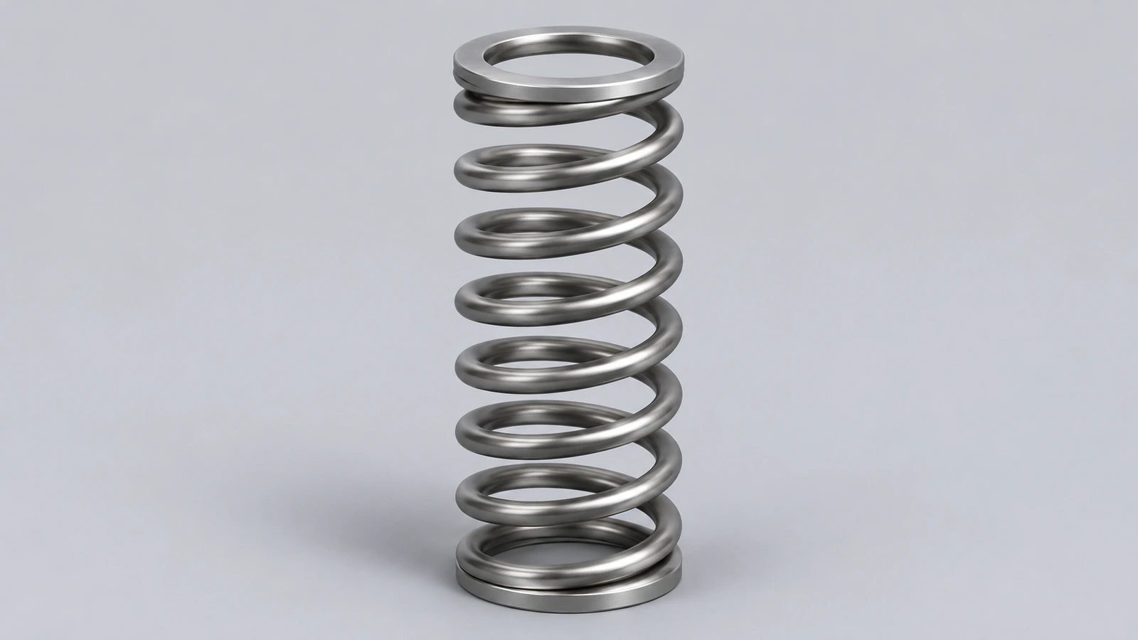
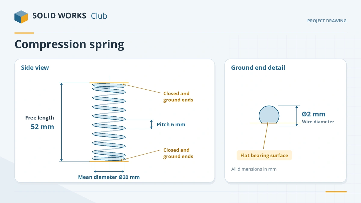
A real compression spring has closed ends — the last coils touch — and the ends are ground flat so it stands upright. SOLIDWORKS models that with a variable-pitch helix and a cut. This project builds a 2 mm wire spring with 10 total coils, 8 of them active, and checks free length and solid length against the standard formulas.
 Kevin Walsh
- Level
- Project
- Time
- 30 min
- Material
- Mild steel, 7.85 g/cm³
Specification
| Parameter | Value |
|---|---|
| Wire diameter d | 2 mm |
| Mean diameter D | 20 mm |
| Total coils Nt | 10 |
| Active coils Na = Nt − 2 | 8 |
| Pitch of active coils p | 6 mm |
| Free length p·Na + 2d | 52 mm |
| Solid length d·Nt | 20 mm |
The key dimensions
Step by step
1. Sketch the base circle
On the Top plane draw a Ø20 circle — the mean diameter.
2. Variable-pitch helix
Insert the Helix/Spiral curve, choose Variable pitch and fill the region table: pitch equal to the wire diameter for the end coils, 6 mm for the active coils. Use a start angle of 0 so the profile is easy to place.
3. Sweep the wire
Sweep along the helix using the Circular Profile option with a 2 mm diameter, or sketch a Ø2 circle on a plane normal to the helix end with a Pierce relation.
4. Grind the ends
Cut the first and last coils flat with planes tied to the ends of the sweep — a plane cut is lighter than a swept cut and follows the helix if it changes.
5. Free and compressed configurations
Add a configuration for the compressed state. In Simulation, replace the spring with a spring connector rather than meshing the coil.
Check your result
- Overall height after grinding: 52 mm free length.
- Compressed until the coils touch, it would measure the 20 mm solid length.
- The Measure tool gives the path length, not the true wire length, because it ignores bending.
This project has no download: the numbers above are the check. Build it from the specification and compare.
Commands used
Show solution
- Sketch the base circle. On the Top plane draw a Ø20 circle — the mean diameter.
- Variable-pitch helix. Insert the Helix/Spiral curve, choose Variable pitch and fill the region table: pitch equal to the wire diameter for the end coils, 6 mm for the active coils. Use a start angle of 0 so the profile is easy to place.
- Sweep the wire. Sweep along the helix using the Circular Profile option with a 2 mm diameter, or sketch a Ø2 circle on a plane normal to the helix end with a Pierce relation.
- Grind the ends. Cut the first and last coils flat with planes tied to the ends of the sweep — a plane cut is lighter than a swept cut and follows the helix if it changes.
- Free and compressed configurations. Add a configuration for the compressed state. In Simulation, replace the spring with a spring connector rather than meshing the coil.
Sources
- GoEngineer — How to make a helix in SOLIDWORKS (Jul 2018)
- UPenn MEAM.Design — Sketch features: Helix/Spiral
- SOLIDWORKS Blog — Seven simple tips for modeling springs (Sep 2012)
- TriMech — How to model a spring in SOLIDWORKS
- Visiativ myCAD — How do I design a spring with SOLIDWORKS? (Mar 2025)
- Newcomb Spring — How to measure a compression spring
- AmesWeb — Compression spring formulas and definitions
Checked November 2026. SOLID WORKS Club is independent; menu names can differ slightly between releases.
Frequently asked questions
How many active coils does a spring with closed ends have?
+
Total coils minus two: the closed end coils do not deflect.
What is the solid length of a closed and ground spring?
+
Wire diameter times total coils — 2 × 10 = 20 mm for this spring.
Related
- How to model a bottle with a thread in SOLIDWORKSModel a bottle in SOLIDWORKS: revolved body with a shoulder arc, shell and a neck thread made with the Thread feature's bottle profile or a sweep along a helix.
- How to make a helical gear in SOLIDWORKSModel a helical gear in SOLIDWORKS: normal and transverse module, helix angle, the tooth twisted along the face width, and checks for pitch and tip diameter.
- SOLIDWORKS SweepHow to use Swept Boss/Base and Swept Cut in SOLIDWORKS: profile and path rules, Pierce, circular profiles, orientation, twist and guide curves.
- Intermediate SOLIDWORKS exercises19 intermediate SOLIDWORKS exercises: sweeps, lofts, shells, draft, Hole Wizard and three small assemblies, each with a drawing, STEP file and check mass.