Project 1
How to make a spur gear in SOLIDWORKS
A spur gear is the classic first mechanical project. SOLIDWORKS offers two routes: drag a Toolbox gear in seconds, or model a true involute tooth with an equation-driven curve. The Toolbox tooth is a circular-arc approximation — fine for assemblies, BOMs and motion, not for cutting the gear from the model. This project builds a module 2, 24-tooth gear the accurate way and shows where Toolbox fits.
 Kevin Walsh
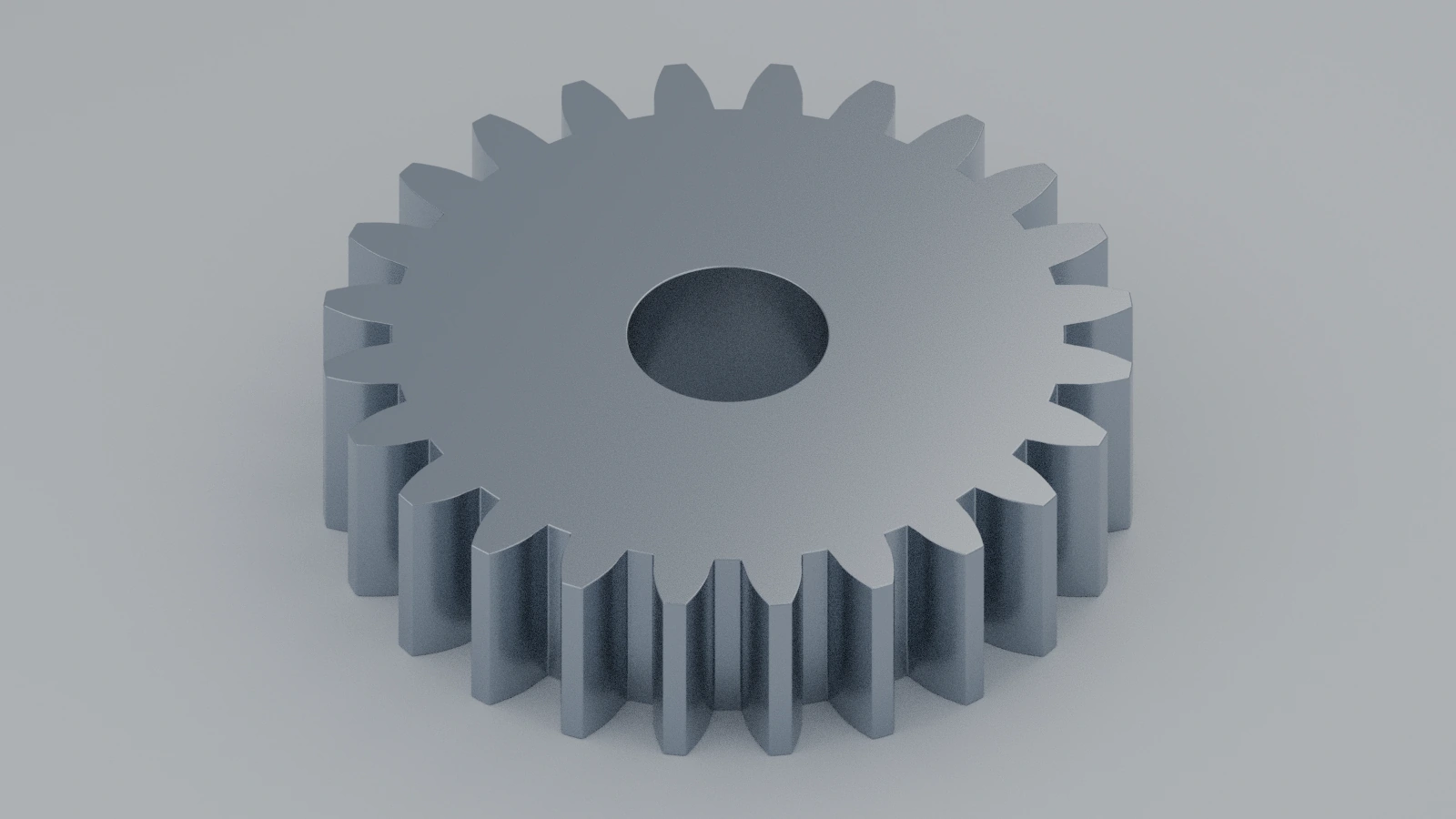
- Level
- Project
- Time
- 45 min
- Material
- Mild steel, 7.85 g/cm³
- Check mass
- 199.80 g
Specification
| Parameter | Value |
|---|---|
| Module m | 2 mm |
| Teeth z | 24 |
| Pressure angle | 20° |
| Pitch diameter d = m·z | 48 mm |
| Tip diameter m(z + 2) | 52 mm |
| Root diameter m(z − 2.5) | 43 mm |
| Base circle d·cos 20° | 45.11 mm |
| Face width / bore | 15 mm / Ø10 |
The drawing
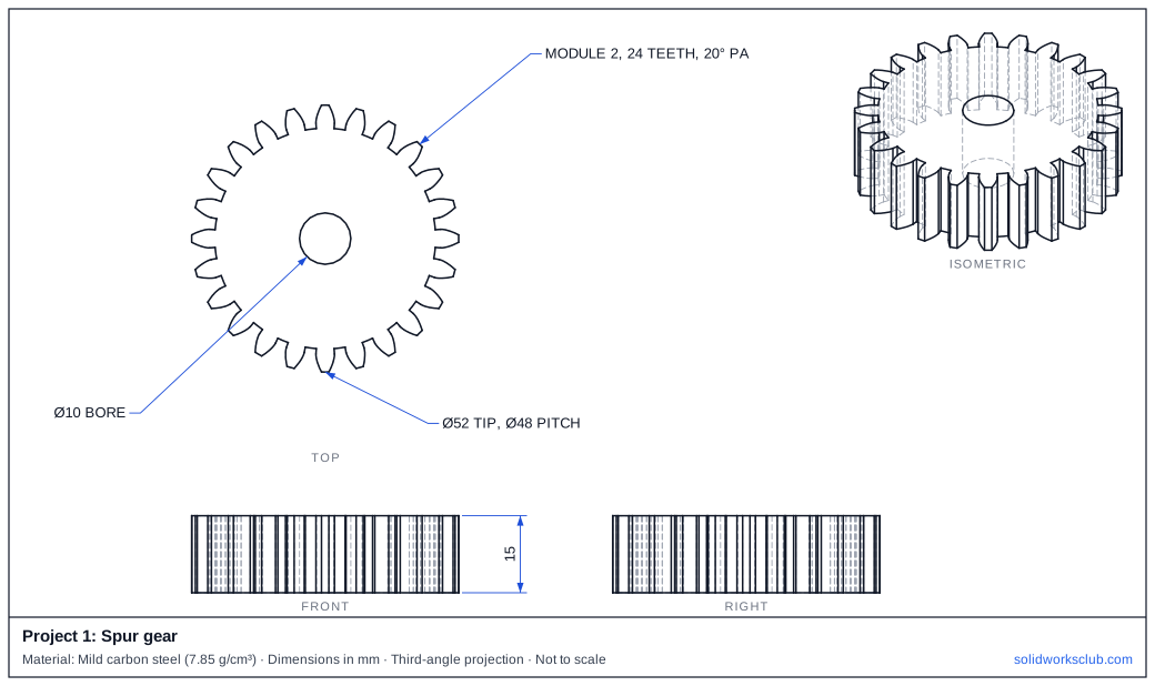
Step by step
1. Sketch the circles
On the Front plane draw construction circles for the pitch (Ø48), base (Ø45.11), tip (Ø52) and root (Ø43) diameters. Drive them from global variables m and z so the gear can be resized.
2. Draw one involute flank
Use an equation-driven curve with the parametric option for the involute, from the base circle out to the tip circle. Sketch only half a tooth and mirror it — this keeps rebuilds fast.
3. Close the tooth
Join the flanks with an arc on the tip circle, add radial lines down to the root circle, and mirror about the tooth centreline. Tooth thickness at the pitch circle is πm/2 = 3.14 mm.
4. Extrude and pattern
Extrude the gear blank (root circle) 15 mm, add the tooth, then Circular Pattern 24 instances. Cut the Ø10 bore.
5. Or use Toolbox
For an assembly or BOM, open Design Library → Toolbox → ISO → Power Transmission → Gears and drag a Spur Gear in; set module 2, 24 teeth, 20°, face width 15 and the bore in the PropertyManager.
Check your result
- Measure the tip diameter: Ø52.
- Measure across the root: Ø43.
- The pitch circle Ø48 should cut each tooth where its thickness is 3.14 mm.
- Our STEP model (true involute) weighs 199.80 g in mild steel at 7.85 g/cm³ — a Toolbox gear will differ slightly because its teeth are arcs.
Compare your model with the STEP file above — it opens in SOLIDWORKS and most other CAD programs.
Next: project 2 — helical gear.
Download files
Commands used
Show solution
- Sketch the circles. On the Front plane draw construction circles for the pitch (Ø48), base (Ø45.11), tip (Ø52) and root (Ø43) diameters. Drive them from global variables m and z so the gear can be resized.
- Draw one involute flank. Use an equation-driven curve with the parametric option for the involute, from the base circle out to the tip circle. Sketch only half a tooth and mirror it — this keeps rebuilds fast.
- Close the tooth. Join the flanks with an arc on the tip circle, add radial lines down to the root circle, and mirror about the tooth centreline. Tooth thickness at the pitch circle is πm/2 = 3.14 mm.
- Extrude and pattern. Extrude the gear blank (root circle) 15 mm, add the tooth, then Circular Pattern 24 instances. Cut the Ø10 bore.
- Or use Toolbox. For an assembly or BOM, open Design Library → Toolbox → ISO → Power Transmission → Gears and drag a Spur Gear in; set module 2, 24 teeth, 20°, face width 15 and the bore in the PropertyManager.
Sources
- Hawk Ridge — Model accurate involute spur gears in SOLIDWORKS (Jul 2024)
- Hawk Ridge — Is the Toolbox spur gear a good fit? (Jul 2024)
- Hawk Ridge — Include spur gears in your assemblies with Toolbox (Jul 2024)
- lucidar.me — Insert gears in a SolidWorks assembly (Apr 2019)
- Fictiv — Creating involute gears in CAD (Jun 2022)
- KHK USA — Standards in terminology for gearing (PDF)
- FIRGELLI — Gear blank diameter calculator (Feb 2026)
- Made Good Designs — Spur gear calculator
Checked November 2026. SOLID WORKS Club is independent; menu names can differ slightly between releases.
Frequently asked questions
Is the SOLIDWORKS Toolbox gear a true involute?
+
No. Hawk Ridge explains that the Toolbox spur gear tooth is a constant-radius arc — good for assemblies, BOMs and basic motion, not for stress analysis or manufacturing straight from CAD.
What is the pitch diameter of a gear?
+
Module times number of teeth: d = m·z. A module 2, 24-tooth gear has a 48 mm pitch diameter.
Related
- How to make a helical gear in SOLIDWORKSModel a helical gear in SOLIDWORKS: normal and transverse module, helix angle, the tooth twisted along the face width, and checks for pitch and tip diameter.
- SOLIDWORKS projects14 SOLIDWORKS projects step by step: gears, spring, bottle, bolt and nut, bearing, chair, phone case, drone frame, vise, gearbox and a robot arm.
- Construction geometry and centerlinesHow construction geometry works in SOLIDWORKS: centerlines, For construction, converting entities, and using them as mirror lines, revolve axes and references.
- Intermediate SOLIDWORKS exercises19 intermediate SOLIDWORKS exercises: sweeps, lofts, shells, draft, Hole Wizard and three small assemblies, each with a drawing, STEP file and check mass.