Project 10
How to model a bench vise in SOLIDWORKS
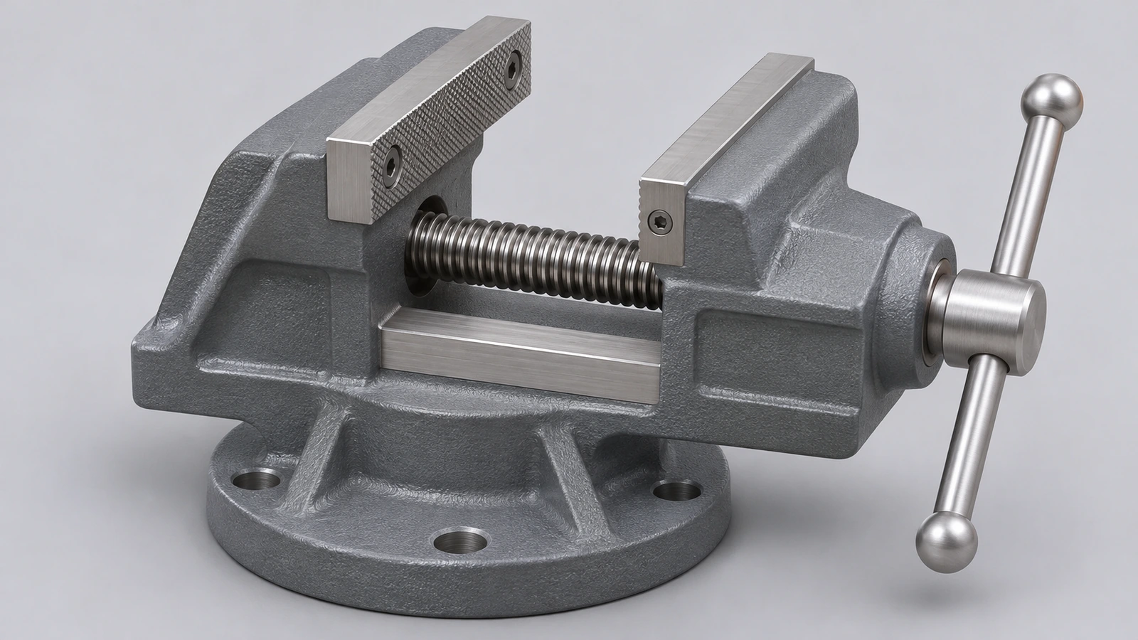
A bench vise is the classic mechanism project: the handle turns the screw, the screw drives the moving jaw. In SOLIDWORKS that motion comes from mates — a screw mate links rotation to travel, and a limit distance mate keeps the jaw between closed and fully open.
 Kevin Walsh
- Level
- Project
- Time
- 60 min
- Material
- Per component (see the check)
- Check mass
- 1,840.77 g total
Specification
| Parameter | Value |
|---|---|
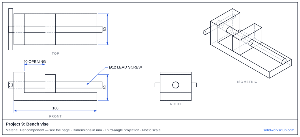
| Body | 160 × 60 base, fixed jaw 20 × 60 × 40 |
| Moving jaw | 20 × 60 × 35 |
| Lead screw | Ø12 × 180 |
| Handle | Ø8 × 80 |
| Opening in the model | 40 mm |
| Thread pitch (screw mate) | Your choice, e.g. 2 mm per revolution |
The drawing
Step by step
1. Parts
Model the body (base plus fixed jaw), the moving jaw with a Ø12 bore, the screw and the handle as separate parts.
2. Basic mates
Fix the body. Moving jaw: coincident on the base top, centred. Screw: concentric with the jaw bores.
3. Screw mate
Mechanical mates → Screw: select the screw's cylindrical face and the moving jaw's bore, set distance per revolution — the thread pitch.
4. Limit the opening
Advanced mates → Limit distance between the jaw faces: minimum 0, maximum the full opening.
5. Test
Rotate the handle both ways; the jaw should travel one pitch per turn and stop at the limits.
Check your result
- Jaw opening in the model: 40 mm.
- Our STEP assembly weighs 1,840.77 g (1,649.40 g grey cast iron + 191.37 g mild steel) (body and jaw in grey cast iron 7.20 g/cm³, screw and handle in mild steel 7.85 g/cm³).
Compare your model with the STEP file above — it opens in SOLIDWORKS and most other CAD programs.
Download files
Commands used
Show solution
- Parts. Model the body (base plus fixed jaw), the moving jaw with a Ø12 bore, the screw and the handle as separate parts.
- Basic mates. Fix the body. Moving jaw: coincident on the base top, centred. Screw: concentric with the jaw bores.
- Screw mate. Mechanical mates → Screw: select the screw's cylindrical face and the moving jaw's bore, set distance per revolution — the thread pitch.
- Limit the opening. Advanced mates → Limit distance between the jaw faces: minimum 0, maximum the full opening.
- Test. Rotate the handle both ways; the jaw should travel one pitch per turn and stop at the limits.
Sources
- GrabCAD — Screw mate in SolidWorks
- Skill-Lync — Assembling a machine vice in SolidWorks (Sep 2024)
- SolidProfessor — Mechanical assembly mates in SOLIDWORKS 2019 (Jan 2019)
- CATI — SOLIDWORKS limit mates (May 2018)
- SOLIDWORKS Tech Blog — Animating rotary motion
Checked November 2026. SOLID WORKS Club is independent; menu names can differ slightly between releases.
Frequently asked questions
How does the screw mate work?
+
It makes two parts concentric and links rotation of one to linear travel of the other by a distance per revolution.
How do I stop the jaw at its limits?
+
Add a Limit Distance mate (Advanced Mates) with the minimum and maximum opening.
Related
- How to design a 3D-printed enclosure in SOLIDWORKSDesign a 3D-printed electronics enclosure in SOLIDWORKS: 2 mm walls, a lid with a locating lip and 0.3 mm clearance, snap-fit rules, and STL or 3MF export.
- How to design a drone frame in SOLIDWORKSDesign a 250-class quadcopter frame in SOLIDWORKS: 250 mm motor-to-motor diagonal, 16 × 19 mm motor holes, 30.5 × 30.5 flight controller mount, DXF for cutting.
- SOLIDWORKS mechanical matesHow to use SOLIDWORKS mechanical mates: Cam, Slot, Hinge, Gear, Rack and Pinion, Screw and Universal Joint, with ratios and how they simulate mechanisms.
- Intermediate SOLIDWORKS exercises19 intermediate SOLIDWORKS exercises: sweeps, lofts, shells, draft, Hole Wizard and three small assemblies, each with a drawing, STEP file and check mass.