Simulation · Lesson 3
Fixtures, loads and contacts
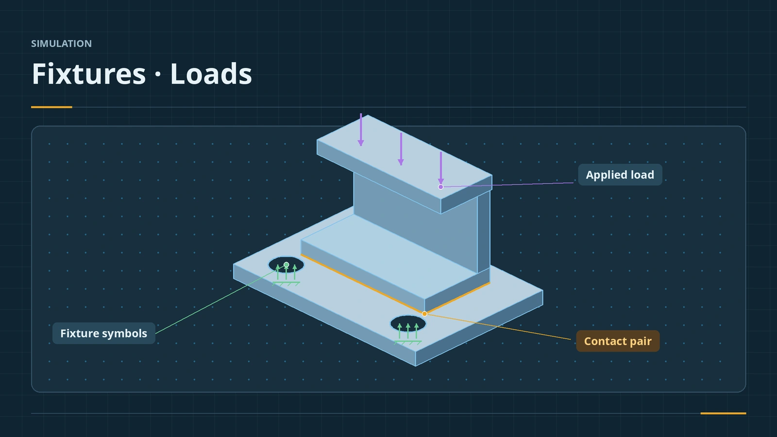
Boundary conditions decide whether an FEA result means anything. Fixtures say how the part is held, loads say what pushes on it, and contacts say how parts in an assembly touch. Too stiff a fixture hides real deflection; too loose and the model flies away. Match them to how the part is really supported.
 Kevin Walsh
Where to find it
Study tree → right-click Fixtures / External Loads / Connections
Load types
| Load | Use |
|---|---|
| Force / Torque | Point-like or distributed forces on faces, edges, vertices |
| Pressure | Uniform or varying pressure on faces |
| Gravity / Centrifugal | Self-weight, rotation |
| Bearing Load | Shaft loads on cylindrical faces |
| Remote Load / Mass | Parts not modelled; rigid or distributed |
| Temperature | Thermal expansion; or results from a thermal study |
Fixtures must stop rigid-body motion before loads are applied. In assemblies, contacts play the role mates play in CAD.
Step by step
-
1
Pick a fixture type
Right-click Fixtures: Fixed Geometry removes all six degrees of freedom; Roller/Slider lets a face slide in its plane; Fixed Hinge lets a cylindrical face rotate.
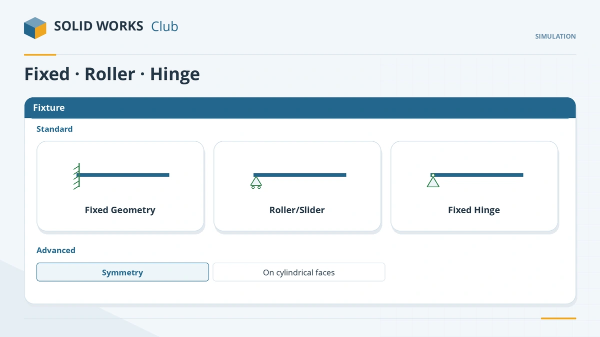
Pick the fixture that matches how the part is really held. -
2
Apply loads
Right-click External Loads: Force, Torque, Pressure, Gravity, Centrifugal, Bearing Load, Remote Load/Mass, Temperature.
-
3
Check contacts in assemblies
In Connections, Global Contact is Bonded by default. Add a local Contact Set with No Penetration only where parts can separate.
-
4
Compare load placement
On the beam, move the 100 N load from the end face to a face at mid-length and re-run.
Common mistakes
- Fixed Geometry on a face that should slide — the model becomes too stiff.
- Global contact switched to No Penetration — slow to solve and parts can fly apart; use local contact sets.
- Remote Mass without a Gravity load — it has no effect.
Lesson 3 of 6 in the simulation course.
Practice
Move the 100 N load from the beam's free end to mid-length (100 mm from the fixture). Check: the tip deflection drops to about 5/16 of the end-load value — δ = 5FL³/(48EI) at the tip, about 0.24 mm for E = 210 GPa.
Sources
- GoEngineer — Degrees of freedom and fixtures (Jul 2024)
- SOLIDWORKS Tech Blog — Getting started: fixtures and loads (Nov 2018)
- GoEngineer — Using remote loads (Apr 2022)
- SOLIDWORKS Tech Blog — Get connected with contacts (Nov 2016)
- GoEngineer — Simulation global contact explained (Feb 2018)
- CATI — Contact hierarchy in SOLIDWORKS Simulation (May 2018)
Checked November 2026. SOLID WORKS Club is independent; menu names can differ slightly between releases.
Frequently asked questions
What fixture types does SOLIDWORKS Simulation have?
+
Standard: Fixed Geometry, Roller/Slider and Fixed Hinge. Advanced: on flat, cylindrical or spherical faces, symmetry, cyclic symmetry and reference geometry.
What is a remote load?
+
A load or mass applied at a point away from the model, connected rigidly or distributed — useful for parts you do not model.
What is the difference between bonded and no penetration contact?
+
Bonded makes parts act as one. No penetration stops them passing through each other but lets them separate; it is slower to solve.
Which contact setting wins?
+
A local contact set overrides component contact, which overrides global contact.
Related
- Your first static studyRun your first SOLIDWORKS static study: add-in, material, fixtures, loads, contacts, mesh and run, then check the deflection against beam theory.
- Meshing in SOLIDWORKS SimulationSOLIDWORKS Simulation meshing: blended curvature-based mesher, density slider, mesh controls, draft vs high quality elements, aspect ratio, convergence.
- SOLIDWORKS standard matesHow to use SOLIDWORKS standard mates: coincident, parallel, perpendicular, tangent, concentric, lock, distance and angle, Quick Mates and lock rotation.
- Results and factor of safetyRead SOLIDWORKS Simulation results: displacement, von Mises stress, factor of safety plots, probes, reports, and why peaks at sharp corners mislead.