Advanced parts · Lesson 6
SOLIDWORKS configurations
Configurations are variants of one part or assembly stored in the same file: a bolt in several lengths, a bracket with and without holes, a simplified version for big assemblies. Each configuration can have its own dimension values, suppressed or active features, material and properties. You switch between them in the ConfigurationManager.
 Kevin Walsh
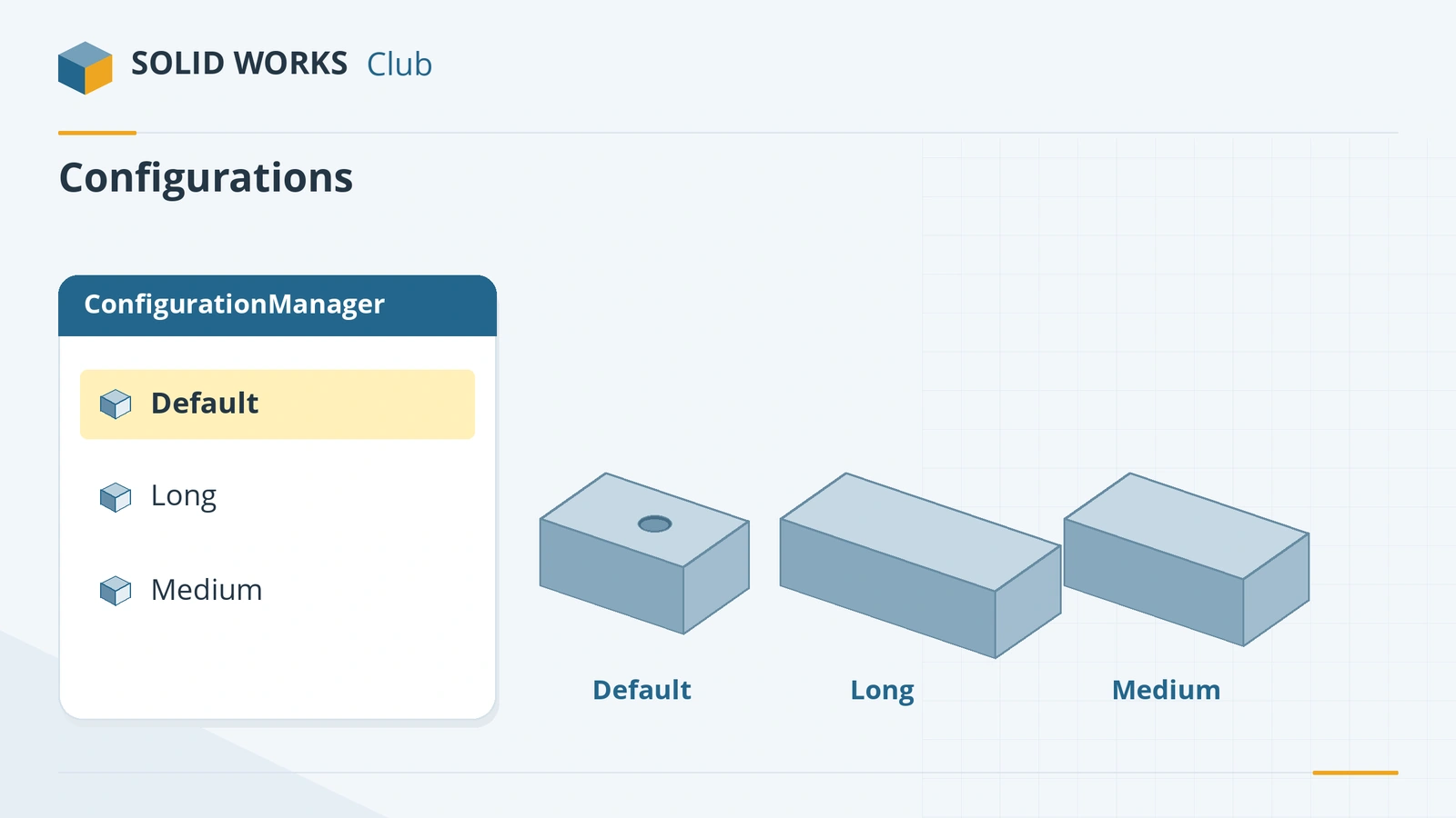
Where to find it
ConfigurationManager tab (left panel); right-click a dimension or feature → Configure
Configuration tools
| Tool | Use |
|---|---|
| Add Configuration | Right-click in the ConfigurationManager |
| Configure Dimension / Feature / Material | Right-click the item; edit values per configuration in a table |
| Suppress per configuration | Edit → Suppress → This, All or Specified configurations |
| Configuration Table | Saved table of configured values in the Tables folder (auto-created since 2022) |
| Derived configuration | Child linked to a parent; overridden cells shown in yellow |
| Design table | Excel sheet driving many configurations — see design tables |
| Configuration Publisher | Lets assemblies insert a configuration by choosing attributes (needs a design table) |
In assemblies, a subassembly without the configurations you need breaks the chain at the top level — configure the subassembly itself. Next: drive many configurations from Excel with design tables.
Practise it: add a compressed configuration to the compression spring.
Step by step
-
1
Build and name the part
Extrude an 80 × 50 mm Center Rectangle 20 mm and cut a Ø10 hole through the centre. Rename the length dimension to Length and the hole feature to Hole — named items are much easier to configure.
-
2
Add a second configuration
Open the ConfigurationManager tab, right-click the part name → Add Configuration, name it Long. The default configuration stays as the original.
-
3
Configure the dimension and feature
Right-click the Length dimension → Configure Dimension. In the table, set Long to 120. Right-click Hole → Configure Feature and tick Suppress for Long.
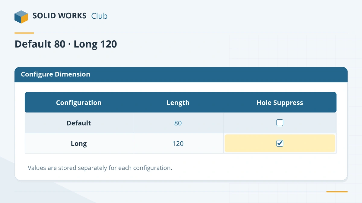
Set values per configuration in the Configure table. -
4
Switch configurations
Double-click each configuration in the ConfigurationManager and watch the part change.
Common mistakes
- Changing a dimension for all configurations when you meant one. Check the configuration scope before accepting changes, or use the Configure table.
- New features appearing in every configuration. Turn on Suppress new features and mates in the configuration's properties if they should only exist where you add them.
- Using configurations for colours or visibility only — display states are lighter.
- Unnamed dimensions (D1@Sketch1) — rename them first.
Lesson 6 of 16 in the advanced parts course.
Practice
Make the two configurations above. Check: Default — volume 78,429.20 mm³ (80 × 50 × 20 with a Ø10 hole); Long — 120,000 mm³ (120 × 50 × 20, hole suppressed).
Sources
- CATI — Configurations part 1: basics
- Solid Solutions — A simple guide to configurations (Jun 2025)
- SOLIDWORKS Help 2024 — Editing configurations
- Hawk Ridge — Utilizing configurations
- Solid Solutions — How to use Configuration Tables (May 2022)
- TriMech — How to use configurations
- SOLIDWORKS Tech Blog — Benefits of derived configurations
- Hawk Ridge — Overview of display states
- Javelin — Display states vs configurations (Sep 2022)
- SOLIDWORKS Tech Blog — Configuration Publisher (2018)
Checked November 2026. SOLID WORKS Club is independent; menu names can differ slightly between releases.
Frequently asked questions
What are configurations in SOLIDWORKS?
+
Variants of a part or assembly stored in one file. Each can have different dimensions, suppressed features, materials and properties.
How do I add a configuration?
+
In the ConfigurationManager, right-click the part name and choose Add Configuration, or type a new name in the Configure Dimension or Feature table.
What is a derived configuration?
+
A child configuration linked to a parent. It inherits the parent's values until you override them.
What is the difference between configurations and display states?
+
Configurations change geometry. Display states change only appearance and visibility, and use much less computing — use them when only the look changes.
Related
- SOLIDWORKS design tablesHow to create a design table in SOLIDWORKS: the Excel requirement, auto-create, dimension and $PRP@ columns, edit options and common mistakes.
- SOLIDWORKS equationsHow to use equations in SOLIDWORKS: the Equations dialog, typing = in a dimension, units, configurable equations, and IIF statements to suppress features.
- SOLIDWORKS global variablesHow to create global variables in SOLIDWORKS, use them in dimensions and equations, avoid the units pitfall, and link them to an external text file.
- SOLIDWORKS running slow — how to speed it upSpeed up a slow SOLIDWORKS with Performance Evaluation, large assembly settings, lightweight mode, image quality, local files and the right graphics setup.