Project 7
How to design a chair in SOLIDWORKS
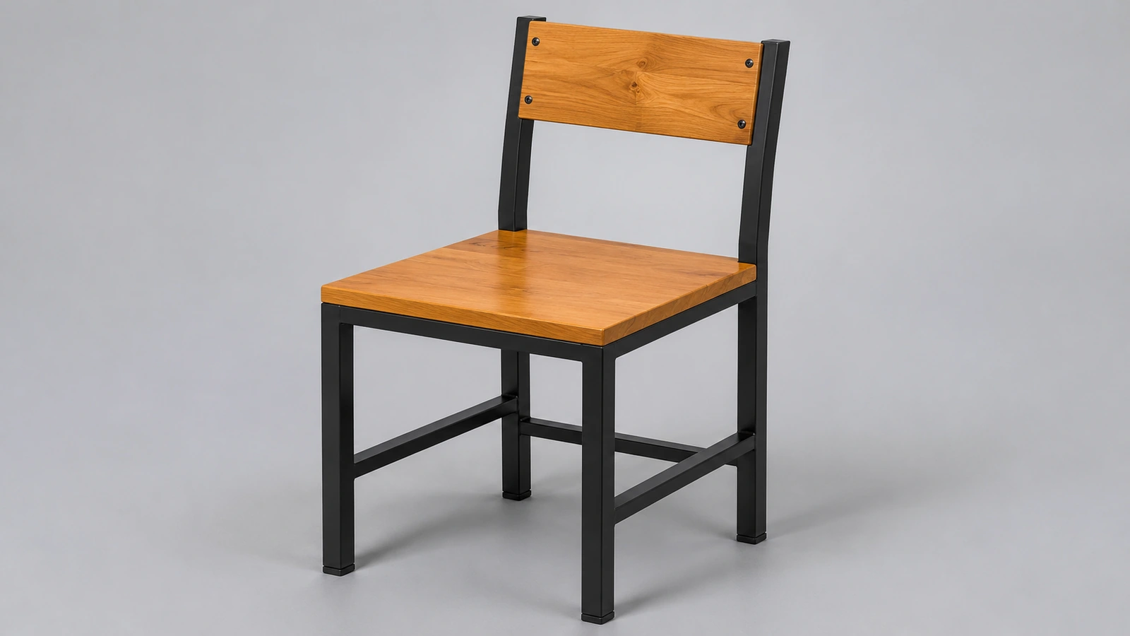
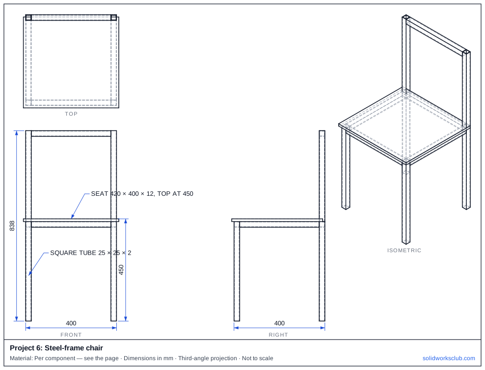
A chair is a good weldment project: a layout sketch, square tube members and a seat board. Ergonomic guides put general seat height and depth at about 400–450 mm; this chair has its seat top at 450 mm and a 420 × 400 mm seat. The cut list then gives every tube length for the workshop.
 Kevin Walsh
- Level
- Project
- Time
- 60 min
- Material
- Steel frame 7.85 g/cm³, timber seat
- Check mass
- 6,213.81 g frame
Specification
| Parameter | Value |
|---|---|
| Seat height (top of seat) | 450 mm |
| Seat board | 420 × 400 × 12 mm |
| Frame | Square tube 25 × 25 × 2 |
| Overall height | 838 mm |
| Footprint | 400 × 400 mm (tube centres 375) |
The drawing
Step by step
1. Layout sketch
A 3D sketch of four legs to 438 mm, side and front rails under the seat, and two back posts with a top rail.
2. Structural members
Weldments → Structural Member, square tube 25 × 25 × 2. Group the legs, rails and back so corner treatments work.
3. Trim the joints
Use Trim/Extend where rails meet legs; check the cut list for one length per member type.
4. Seat board
Extrude a 420 × 400 × 12 board on top of the frame as a separate body — or make it a part in an assembly if it has its own part number.
5. Check ergonomics
Seat depth 380–420 mm and seat height not above knee height are typical recommendations for work seats; a slight backward tilt of the seat (3–5°) is common.
Check your result
- Seat top at 450 mm.
- Steel frame mass 6,213.81 g (tube 25 × 25 × 2 at 7.85 g/cm³); the seat board adds its own material.
- Seat board volume 2,016,000 mm³ — multiply by your timber's density.
Compare your model with the STEP file above — it opens in SOLIDWORKS and most other CAD programs.
Next: project 8 — phone case.
Download files
Commands used
Show solution
- Layout sketch. A 3D sketch of four legs to 438 mm, side and front rails under the seat, and two back posts with a top rail.
- Structural members. Weldments → Structural Member, square tube 25 × 25 × 2. Group the legs, rails and back so corner treatments work.
- Trim the joints. Use Trim/Extend where rails meet legs; check the cut list for one length per member type.
- Seat board. Extrude a 420 × 400 × 12 board on top of the frame as a separate body — or make it a part in an assembly if it has its own part number.
- Check ergonomics. Seat depth 380–420 mm and seat height not above knee height are typical recommendations for work seats; a slight backward tilt of the seat (3–5°) is common.
Sources
- Javelin — A complete guide to SOLIDWORKS weldments (May 2024)
- Javelin — Multibody part vs assembly (Jun 2023)
- Topmax Furniture — Basic dimensions of seats (May 2025)
- Studio Matrx — Human dimensions: furniture
Checked November 2026. SOLID WORKS Club is independent; menu names can differ slightly between releases.
Frequently asked questions
What seat height should a chair have?
+
Design guides give about 400–450 mm for general chairs; work seats should not be higher than the user's knee height.
Weldment or assembly?
+
A weldment keeps the frame in one part with a cut list. Use an assembly when the seat and frame have their own part numbers.
Related
- How to design a phone case in SOLIDWORKSDesign a phone case in SOLIDWORKS around a phone body: 0.3 mm clearance, 1.5 mm walls, a 1 mm screen lip and a camera opening, sized for TPU 3D printing.
- How to model a ball bearing in SOLIDWORKSModel a 6201 deep groove ball bearing in SOLIDWORKS: 12 × 32 × 10 envelope, inner and outer rings with raceways, seven balls, a circular pattern and mates.
- Structural Member — your first weldment frameBuild a SOLIDWORKS weldment frame with Structural Member: layout sketch, standard, type and size, groups, corner treatment, trim order and locating the profile.
- Intermediate SOLIDWORKS exercises19 intermediate SOLIDWORKS exercises: sweeps, lofts, shells, draft, Hole Wizard and three small assemblies, each with a drawing, STEP file and check mass.