Weldments · Lesson 1
Structural Member — your first weldment frame
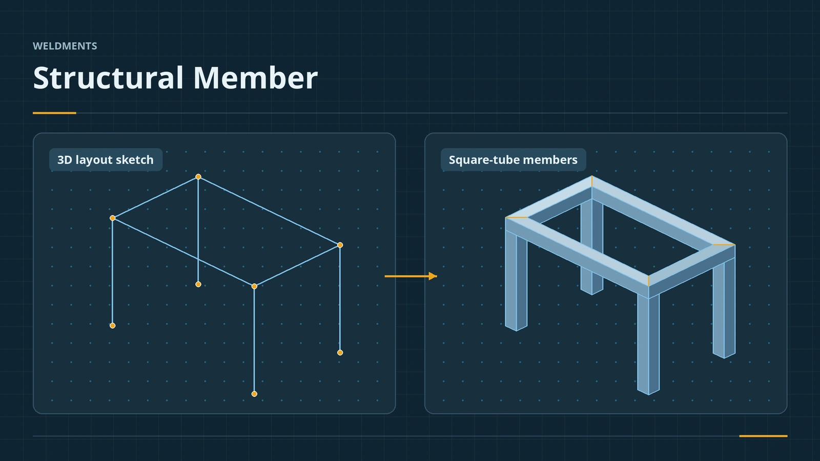
Structural Member sweeps a standard profile — square tube, pipe, angle, channel or beam — along the lines of a layout sketch. Each member becomes a separate body in one weldment part. Segments are organised in groups that share a profile, and corner treatment decides how members meet: mitred or butted.
 Kevin Walsh
Where to find it
Weldments tab → Structural Member (turn on Weldments tab via right-click on CommandManager)
Options
| Option | Use |
|---|---|
| Standard / Type / Size | Picks the profile from the weldment profiles folder |
| Groups / New Group | Segments sharing one profile; contiguous or parallel |
| Apply corner treatment | End Miter, End Butt1, End Butt2 for the group |
| Gap | Gap between members of a group, or per corner |
| Mirror profile / Alignment / Rotation angle | Orient the profile on the path |
| Locate Profile | Choose another pierce point than the sketch origin |
| Merge miter trimmed bodies | Combine mitred bodies (off by default) |
Run Select Chain before the command to pick connected lines quickly — there is no chain selection inside it. Since 2019, Structure System offers a second way to build frames with members made from points, lengths and planes. Weldments are in every SOLIDWORKS package. Layout sketches are covered in 3D sketches.
Practise it: build the frame of the steel-frame chair.
Step by step
-
1
Sketch the layout
In a new part, open a 3D Sketch. Draw a 1000 × 500 rectangle on the XZ plane and four 400 mm vertical lines down from its corners. Lines and arcs work as paths; splines do not.
-
2
Add the frame group
Weldments tab → Structural Member. Standard iso, type square tube, a size from your library (for example 20 x 20 x 2). Select the four rectangle lines. Tick Apply corner treatment → End Miter.
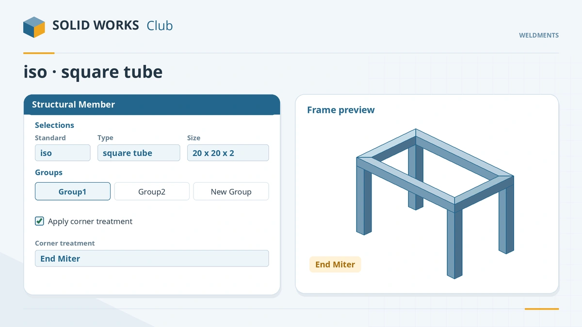
Pick standard, type and size; groups share a profile and a corner treatment. -
3
Add the legs as a new group
Click New Group and select the four vertical lines — parallel segments can share a group. The legs are trimmed by the frame because group 1 comes first in the trim order. Click the tick.
-
4
Look at the tree
A Weldment feature and a Cut list folder appear. Each member is a body; identical bodies are collected into one cut list item.
Common mistakes
- Three or more segments meeting at one vertex in the same group — use New Group.
- Expecting a second Structural Member feature to trim against the first — joints between features need Trim/Extend.
- Profile on the wrong side of the line — use Locate Profile to pick another pierce point.
Lesson 1 of 7 in the weldments course.
Practice
Build the 1000 × 500 frame with four 400 mm legs. Check: the cut list has 3 items with quantities 2, 2 and 4 — the long rails, the short rails and the legs, eight bodies in all.
Sources
- CATI — Weldments from profiles to cut lists, part 1 (Feb 2014)
- Engineers Rule — A beginner's guide to SOLIDWORKS weldments (May 2016)
- GoEngineer — Weldment profiles and weldment tools guide (Jan 2022)
- GoEngineer — Designing a trailer using weldments (Jun 2020)
- Dassault Systèmes — Working with Weldments, SolidPractices (rev. May 2025)
- Solid Solutions — Weldments structural member corners (Mar 2014)
- Javelin — Weldment trim order (Feb 2019)
- TriMech — Locating structural members in weldments
- Javelin — Structural member chain selection (Sep 2017)
- ST Technica — SolidWorks weldment gap (2011)
- Engineers Rule — New Structure System tools in 2019 (May 2019)
- GoEngineer — Comparing SOLIDWORKS packages (Jul 2026)
Checked November 2026. SOLID WORKS Club is independent; menu names can differ slightly between releases.
Frequently asked questions
How do I make a weldment frame in SOLIDWORKS?
+
Sketch the layout (2D or 3D), click Structural Member, choose standard, type and size, and select the sketch segments as paths.
What is a group in Structural Member?
+
A set of segments sharing one profile. They must be contiguous or parallel, and each group has its own corner treatment and trim order.
What corner treatments are there?
+
End Miter, End Butt1 and End Butt2. Click the dot at a corner to override one corner.
Why are only a few profiles available?
+
A new installation ships a few ANSI Inch and ISO sizes. Download full standards from Design Library → SOLIDWORKS Content → Weldments.
Related
- Custom weldment profilesCreate custom SOLIDWORKS weldment profiles: sketch the section, save as .sldlfp, folder structure, File Locations, pierce points, configurations and properties.
- Trim/Extend for weldment membersTrim and extend SOLIDWORKS weldment members: End Trim, End Miter, End Butt1 and End Butt2, face or body boundaries, simple vs coped cuts and weld gap.
- Weldment cut listsHow the SOLIDWORKS weldment cut list works: grouping identical bodies, LENGTH and ANGLE properties, bounding boxes, properties and the cut list table.
- 3D sketches in SOLIDWORKSHow to draw a 3D sketch in SOLIDWORKS: start it, switch planes with Tab, use the space handle and Along X/Y/Z relations, and build sweep paths.