Errors & Fixes
SOLIDWORKS rebuild errors and warnings — how to fix them
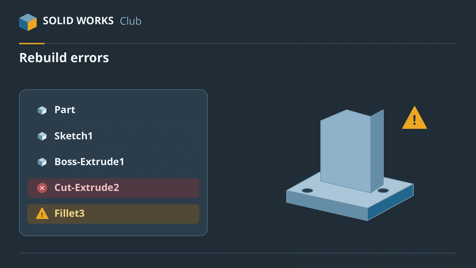
SOLIDWORKS rebuilds features from the top of the FeatureManager tree down. When a feature cannot be rebuilt — usually because something it depends on has changed or disappeared — its name turns red and an error icon appears. A yellow warning means the feature still rebuilt, but something is not right. The rule that saves the most time: always fix the first error in the tree first, because the ones below it are often caused by it.
 Kevin Walsh
Applies to: SOLIDWORKS 2022–2027 parts and assemblies.
Most likely causes
- Dangling dimensions or relations — the edge or face they used is gone (most common)
- An earlier feature or sketch was edited, deleted or reordered (common)
- Sketch errors: over-defined, open or self-intersecting profile (common)
- Zero-thickness geometry — faces that touch along a line or point (occasional)
- Fillets, chamfers, shells or drafts that cannot fit the geometry (occasional)
- Broken external references from an assembly (in-context parts)
What the icons mean
| Icon in the tree | Meaning |
|---|---|
| Red text with an error icon | Feature cannot be built |
| Yellow text with a warning triangle | Feature built, but with a problem |
| Error or warning next to the part name | There is a problem somewhere below |
(-), (+), (?) before a sketch |
Under-defined, over-defined, cannot be solved |
From the official FeatureManager tree conventions. The full list of prefixes for sketches and mates is in sketch errors and mate errors.
The fastest way through a tree full of errors
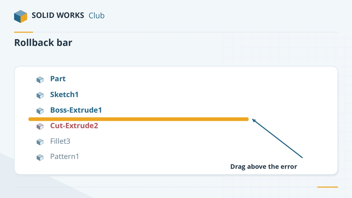
- Drag the rollback bar to the top, below the origin.
- Move it down one feature at a time until the first red item appears.
- Fix that feature (sketch, references, end condition).
- Continue down. Many errors further down disappear on their own.
Write models that break less often
- Dimension sketches to planes and the origin rather than to model edges, which change when you add fillets or chamfers.
- Add fillets and chamfers last.
- Fully define sketches — a black sketch cannot move unexpectedly.
- Name important features so you can find them when something fails.
- In assemblies, keep in-context references to a minimum — see missing references.
Building sketches that survive changes is covered in the sketching course.
Feature-by-feature guidance: Fillet, Shell and the whole features course.
Dedicated guides: fillet errors, zero-thickness geometry, shell errors and sweep and loft errors.
Fixes, in order
1. Open What's Wrong and start at the top
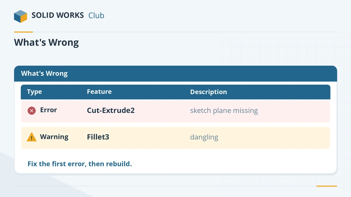
Right-click the part name → What's Wrong, or click the error icon. The dialog lists every error and warning; sort it by feature order. Hover over a feature in the tree to see its message. Fix the highest error in the tree first, rebuild, and look again.
2. Roll back to isolate the error
Drag the rollback bar to just below the first failing feature. Everything below is ignored, so you can see the model as the feature sees it. Edit the feature, then drag the bar back down.
3. Repair dangling sketch references
Edit the sketch of the failing feature. Dangling dimensions and relations point to geometry that no longer exists. Delete them and re-create them on existing edges, or drag the dangling endpoint onto the new edge. Tools → Sketch Tools → Repair Sketch finds gaps and overlaps. More in sketch errors.
4. Fix "sketch plane" and face references
If the face a sketch was on has been removed, right-click the sketch → Edit Sketch Plane and pick a new face or plane. For features that used deleted faces (fillets, drafts, end conditions), edit the feature and reselect the missing faces or edges in its selection boxes.
5. Fix zero-thickness geometry
Would result in zero-thickness geometry means an edge would have more than two faces — typically a cut or boss that just touches existing geometry along a line, such as a cut tangent to a hole. Make it overlap a little or leave a gap, or clear Merge result so it becomes a separate body.
6. Let FeatureXpert fix fillets and drafts
When a fillet or draft fails, the error dialog can offer FeatureXpert, which reorders or splits fillets to make them work. Enable it under System Options → General if you do not see it. Otherwise reduce the radius or fillet fewer edges at a time.
7. Force a full rebuild to check
Ctrl + B rebuilds only changed features; Ctrl + Q rebuilds every feature and is useful to confirm that the model is really clean. Evaluate → Check finds bad geometry. See the keyboard shortcuts for more.
8. Choose what happens on rebuild errors
Tools → Options → System Options → Messages/Errors/Warnings sets whether SOLIDWORKS shows errors on every rebuild and whether it stops, continues or asks when it meets an error. Stopping at the first error is handy when you edit a long tree.
Sources
- TriMech — SOLIDWORKS modelling errors, part one (Jan 2023)
- TriMech — SOLIDWORKS modelling errors, part two (Jan 2023)
- SOLIDWORKS Tech Blog — Troubleshooting with the What's Wrong dialog
- SOLIDWORKS Help 2024 — Error messages overview
- SOLIDWORKS Help 2024 — Zero thickness geometry
- SOLIDWORKS Help 2024 — FeatureManager design tree conventions
- Hawk Ridge — Ctrl+Q, Verification on rebuild and geometry check tools
Checked November 2026. SOLID WORKS Club is independent; menu names can differ slightly between releases.
Frequently asked questions
What is the difference between a rebuild error and a warning?
+
An error (red) means the feature could not be built. A warning (yellow) means it was built, but there is a problem you should check, such as a dangling dimension or an unused reference.
How do I see all rebuild errors in a part?
+
Right-click the part at the top of the FeatureManager tree and choose What's Wrong. The dialog lists every error and warning with its feature, and you can sort it.
What does Ctrl+Q do in SOLIDWORKS?
+
It forces a rebuild of every feature in the part or assembly. Ctrl+B rebuilds only features that changed. Ctrl+Q is slower but confirms that the whole model rebuilds without errors.
What is a dangling dimension?
+
A dimension or relation that refers to geometry that no longer exists — for example an edge removed by an earlier change. It shows in a different colour in the sketch and must be deleted or reattached.
Related
- SOLIDWORKS sketch errors — over defined, unsolvable and open sketchesFix SOLIDWORKS sketch errors: over defined, no solution found, dangling relations, open or self-intersecting contours, with SketchXpert and Repair Sketch.
- SOLIDWORKS mate errors — over defined and failed matesFix SOLIDWORKS mate errors: over defined components, mates not satisfied, conflicting mates and fixed parts, using MateXpert and the Mates folder.
- SOLIDWORKS keyboard shortcutsEvery default SOLIDWORKS keyboard shortcut in a searchable list and a one-page PDF — rebuild, views, zoom, filters, sketch and assembly keys — and customising.
- SOLIDWORKS missing references — unable to locate fileSOLIDWORKS "unable to locate file" when opening an assembly or drawing? How the search order works, how to repair references, and how to rename files safely.