Features · Lesson 13
SOLIDWORKS Thread feature
The Thread feature, added in SOLIDWORKS 2016, models real helical threads on shafts and holes from a library of profiles. Use it when the thread geometry itself matters — 3D-printed parts, realistic renderings, or threads that are not standard. It is much faster to set up than a helix and sweep, but modelled threads are heavy, so keep them out of big assemblies or suppress them in a simplified configuration.
 Kevin Walsh
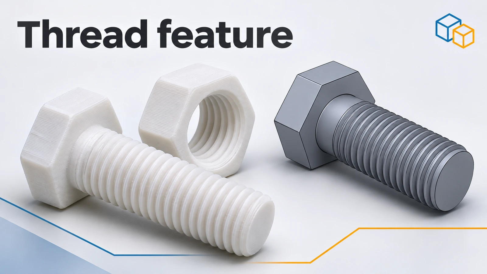
Where to find it
Insert → Features → Thread (also in the Hole Wizard flyout)
Thread feature options
| Option | What it does |
|---|---|
| Edge / start location | Where the thread starts; an offset can move it |
| Type and size | Profile library: die (external) or tap (internal), inch or metric |
| Cut / Extrude thread | Removes material from a shaft, or adds thread material |
| End condition | Thread length |
| Right / left hand | Thread direction |
| Trim with start/end face (2017+) | Ends the thread flush with the faces |
| Multiple starts (2017+) | Multi-start threads |
Before the Thread feature, threads were made with a helix and a sweep — still useful for unusual profiles, but slower: in a CATI test the Thread command rebuilt in about 2.3 s versus 7.25 s for a helical sweep.
Practise it: the neck of the threaded bottle and the M10 bolt and nut.
Step by step
-
1
Make the shaft
Extrude a Ø10 circle 30 mm — the shaft from the cosmetic thread lesson, without its cosmetic thread.
-
2
Start the Thread feature
Insert → Features → Thread. Pick the circular edge at the end of the shaft as the start location.
-
3
Choose the profile
Pick a metric die profile (dies cut external threads) and size M10. Choose Cut thread, set the end condition to the length you need, and keep right-hand threads unless you need left-hand.
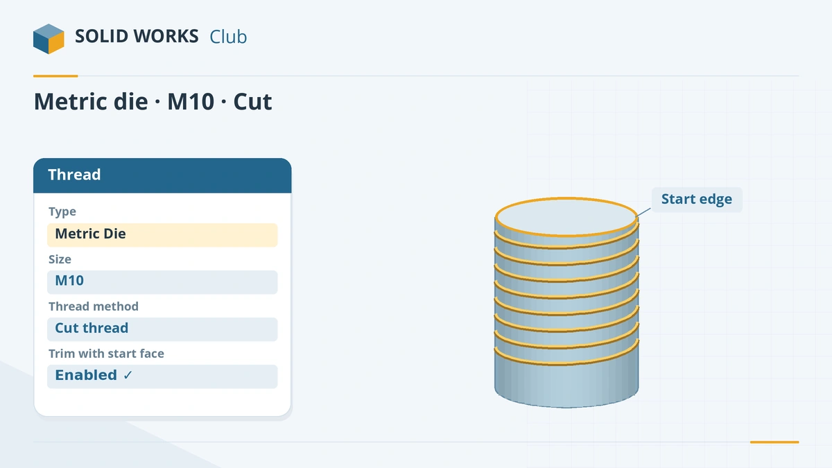
Pick the start edge, a die profile and size, and cut the thread. -
4
Clean up the ends
Tick Trim with start face and Trim with end face (since 2017) so the thread ends flush instead of with a partial turn sticking out.
Common mistakes
- Modelled threads on every fastener in an assembly. They dominate rebuild time — use cosmetic threads unless geometry is needed.
- Tapered or conical faces — the Thread feature does not support them.
- Printed threads with no clearance. Add a small offset; TriMech used about 0.3 mm for a printed cap.
- Missing profile library after a reinstall. Point File Locations to the Thread Profiles folder.
Lesson 13 of 18 in the features course.
Practice
Add an M10 cut thread to the Ø10 × 30 mm shaft. Check: open Evaluate → Performance Evaluation — the Thread feature should be by far the slowest feature in the part. Suppress it and compare the rebuild time.
Sources
- GoEngineer — How to make threads in SOLIDWORKS
- Javelin — SOLIDWORKS 2016 part features (Thread)
- Javelin — SOLIDWORKS 2017 thread enhancements
- GoEngineer — Performance: physical vs cosmetic threads
- CATI — SOLIDWORKS threads compared
- Hawk Ridge — Missing thread profiles
- TriMech — Designing and 3D printing threaded parts
Checked November 2026. SOLID WORKS Club is independent; menu names can differ slightly between releases.
Frequently asked questions
How do I make a real thread in SOLIDWORKS?
+
Use Insert → Features → Thread, pick the edge where it starts, choose a profile and size, and set the length. For external threads choose a die profile; for internal threads a tap profile.
Should I use modelled or cosmetic threads?
+
Cosmetic for nearly everything — they are fast and give drawing callouts. Modelled threads for 3D printing, renderings and special threads.
Why is my part slow after adding a thread?
+
Helical geometry is expensive to rebuild. In one reseller test the Thread feature took 96% of a part's rebuild time. Suppress it in a simplified configuration.
Where are the thread profiles stored?
+
In C:\ProgramData\SOLIDWORKS\SOLIDWORKS 20xx\Thread Profiles, set in System Options → File Locations.
Related
- SOLIDWORKS Cosmetic ThreadHow to add a cosmetic thread in SOLIDWORKS to shafts and holes, show shaded threads, get drawing callouts, and why it beats modelled threads for speed.
- SOLIDWORKS Hole WizardHow to use the SOLIDWORKS Hole Wizard: hole types, standards, sizes and fit, the Type and Positions tabs, cosmetic threads, slots, favourites and Advanced Hole.
- SOLIDWORKS SweepHow to use Swept Boss/Base and Swept Cut in SOLIDWORKS: profile and path rules, Pierce, circular profiles, orientation, twist and guide curves.
- SOLIDWORKS running slow — how to speed it upSpeed up a slow SOLIDWORKS with Performance Evaluation, large assembly settings, lightweight mode, image quality, local files and the right graphics setup.