Features · Lesson 4
SOLIDWORKS reference planes
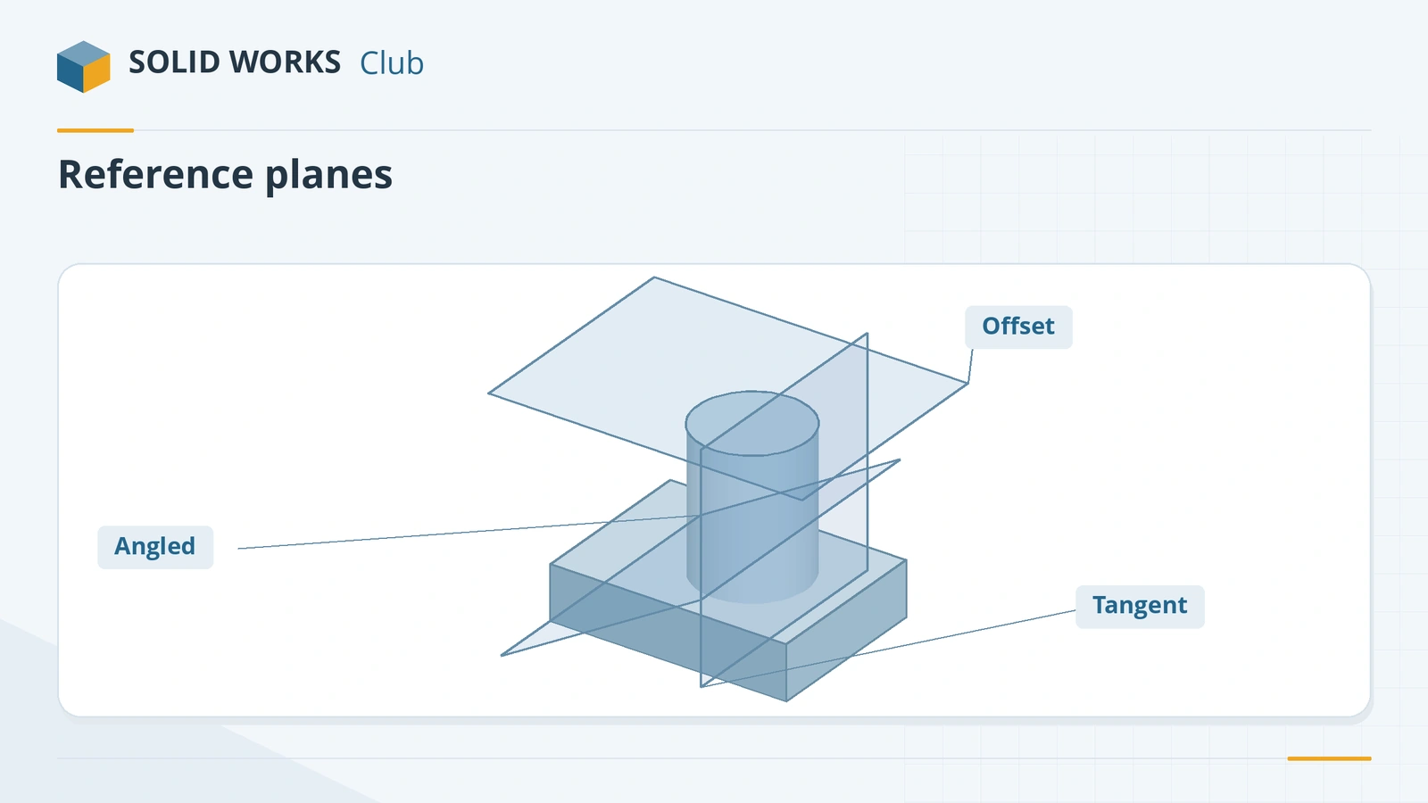
A part starts with three planes — Front, Top and Right — but many features need a sketch somewhere else: at a height above the base, at an angle, tangent to a round face, or square to a path. Reference planes give you those sketch surfaces. You define a plane by up to three references (faces, edges, points or other planes) and a constraint such as offset, angle or tangent, until the PropertyManager says Fully Defined.
 Kevin Walsh
Where to find it
Features tab → Reference Geometry → Plane (Insert → Reference Geometry → Plane)
Common ways to define a plane
| Plane you need | References | Constraint |
|---|---|---|
| Parallel at a distance | A plane or face | Offset distance (set number of planes for several) |
| At an angle | A plane or face + an edge or axis | Angle |
| Between two faces | Two faces (need not be parallel) | Mid Plane |
| Tangent to a round face | A cylinder + a plane (or two cylinders) | Tangent, with an angle to rotate it |
| Through three points | Three points or vertices | Coincident |
| Perpendicular to a line | An edge or sketch line + a point on it | Perpendicular |
| Facing the screen | A point | Parallel to screen |
A shortcut for sweep profiles: select an edge near its end and click Sketch — SOLIDWORKS creates a plane normal to the edge and starts a sketch on it. Since SOLIDWORKS 2025 planes can also be patterned linearly or circularly.
Tangent planes are also how you place text for Wrap. Planes are the backbone of lofts and sweeps; axes are covered in the next lesson.
Step by step
-
1
Build a base block
Extrude a 60 × 60 mm Center Rectangle on the Top Plane, 20 mm up.
-
2
Create an offset plane
Reference Geometry → Plane. As First Reference pick the Top Plane in the flyout tree, choose Offset distance and type 30 mm (flip if it goes down). The message Fully Defined appears; click the tick.
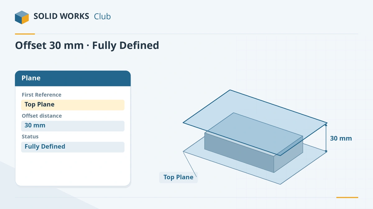
An offset plane is defined by one reference and a distance. -
3
Sketch on the new plane
Select Plane1, start a sketch and draw a Ø20 circle on the origin.
-
4
Extrude down to the block
Extruded Boss/Base, reverse the direction so it points down, and choose Up To Surface → the top face of the block. The cylinder fills the 10 mm gap exactly — and follows if the plane or block moves.
Common mistakes
- Creating a plane that is not fully defined — check the message in the PropertyManager before clicking OK.
- Making a new plane for every offset sketch. Extrude's From option can start at an offset without a plane.
- Building planes on faces that will later change (fillets, cuts). Reference the default planes or stable faces where possible.
Lesson 4 of 18 in the features course.
Practice
Build the block with the plane 30 mm above the Top Plane and the Ø20 cylinder extruded down to the block. Check: total volume 75,141.59 mm³. Change the plane offset to 40 — the cylinder should grow to 20 mm.
Sources
- Solid Solutions — How to create planes (Jul 2023)
- GoEngineer — Creating reference planes (Jan 2022)
- SOLIDWORKS Tech Blog — Basics of reference geometry (2018)
- Javelin — Sketch normal to an edge
- GoEngineer — SOLIDWORKS 2025 parts and features (Nov 2024)
- SOLIDWORKS Help 2024 — End conditions for extrudes
Checked November 2026. SOLID WORKS Club is independent; menu names can differ slightly between releases.
Frequently asked questions
How do I create a plane at an angle in SOLIDWORKS?
+
Pick a plane or face as the first reference and an edge or axis as the second, then choose the angle option and type the angle. The plane rotates about the edge or axis.
How do I make a plane tangent to a cylinder?
+
Pick the cylindrical face and a plane, then set an angle to rotate the tangent plane around the cylinder. Picking two cylinders gives a plane tangent to both.
How do I create several parallel planes at once?
+
In the Plane PropertyManager set the number of planes after the offset distance; SOLIDWORKS creates them evenly spaced.
What is the quickest way to make an offset plane?
+
Hold Ctrl and drag an existing plane in the graphics area, then type the offset distance.
Related
- SOLIDWORKS reference axis and temporary axesHow to create a reference axis in SOLIDWORKS, show temporary axes, and use axes for revolves and angled planes, plus points and coordinate systems.
- SOLIDWORKS LoftHow to use Lofted Boss/Base in SOLIDWORKS: profiles on offset planes, profile order, guide curves, end tangency, and fixing twisted lofts.
- SOLIDWORKS SweepHow to use Swept Boss/Base and Swept Cut in SOLIDWORKS: profile and path rules, Pierce, circular profiles, orientation, twist and guide curves.
- SOLIDWORKS Extruded Boss/BaseHow to use Extruded Boss/Base in SOLIDWORKS: every end condition from Blind to Mid Plane, Direction 2, draft, thin features, Selected Contours and Merge result.