Features · Lesson 5
SOLIDWORKS reference axis and temporary axes
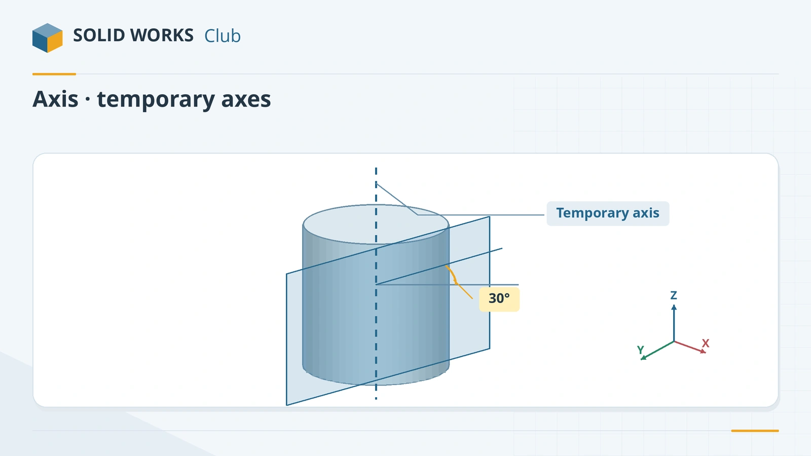
An axis is a straight reference line. Every cylindrical or conical face already has a temporary axis that SOLIDWORKS creates for you — you only need to make it visible. A reference axis is one you create yourself and that appears in the FeatureManager tree, for example along an edge or through two points. Axes are used for revolves, circular patterns, angled planes and concentric mates.
 Kevin Walsh
Where to find it
Features tab → Reference Geometry → Axis; Heads-up toolbar → Hide/Show Items → Temporary Axes
Reference geometry at a glance
| Type | Created by | Typical use |
|---|---|---|
| Temporary axis | Automatically, for every cylindrical or conical face | Revolves, circular patterns, concentric mates |
| Reference axis | Reference Geometry → Axis (from an edge, a round face, points or planes) | An axis that must appear in the tree or be visible |
| Reference plane | Reference Geometry → Plane | Sketching away from the default planes — see reference planes |
| Coordinate system | Origin + axis directions | Measuring, export, mass properties; since 2026 bounding boxes |
| Reference point | Reference Geometry → Point | Sketch positions, plane and axis references |
Circular patterns use an axis as their centre; they are covered in the next course.
Circular patterns around axes: Circular Pattern.
Step by step
-
1
Make a cylinder
Extrude a Ø40 circle on the Top Plane 30 mm up.
-
2
Show the temporary axis
On the heads-up view toolbar open Hide/Show Items (the eye icon) and turn on View Temporary Axes. A dashed axis appears through the centre of the cylinder.
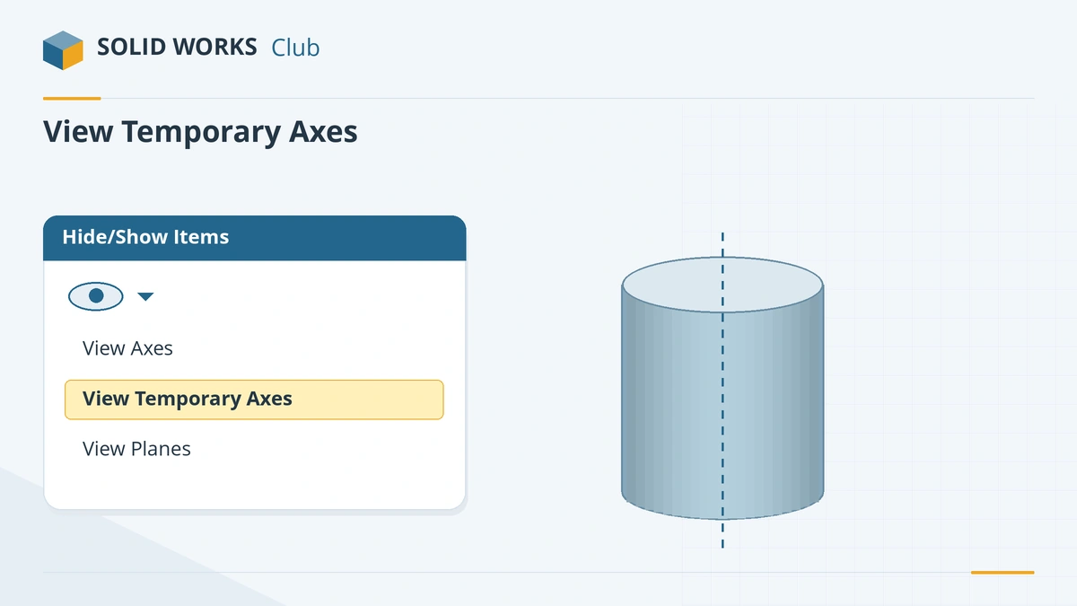
Temporary axes exist for every round face; you only need to show them. -
3
Create a reference axis
Reference Geometry → Axis, select the cylindrical face. SOLIDWORKS creates Axis1 in the tree — it stays even when temporary axes are hidden.
-
4
Use it for an angled plane
Reference Geometry → Plane: first reference Axis1, second reference the Front Plane, choose the angle option and type 30°. You get a plane through the cylinder's axis at 30° to the Front Plane — handy for features placed at an angle around a part.
Common mistakes
- Creating reference axes for every hole. Temporary axes already exist; create a reference axis only when you need it in the tree or need it visible.
- Basing an axis on a face that will be removed later — the axis and everything built on it fail.
- Forgetting that temporary axes are hidden by default and assuming they do not exist.
Lesson 5 of 18 in the features course.
Practice
Build the cylinder, create Axis1 from its face and a plane through Axis1 at 30° to the Front Plane. Check: with Evaluate → Measure, select the new plane and the Front Plane — the angle reads 30°. The cylinder's volume is 37,699.11 mm³.
Sources
- CATI — Basics of reference geometry: axis (2020)
- Solid Solutions — Temporary axis
- SOLIDWORKS Tech Blog — Basics of reference geometry (2018)
- CATI — Reference points
- GoEngineer — SOLIDWORKS 2026 parts and features (Oct 2025)
- Solid Solutions — How to create planes (Jul 2023)
Checked November 2026. SOLID WORKS Club is independent; menu names can differ slightly between releases.
Frequently asked questions
How do I show temporary axes in SOLIDWORKS?
+
Turn on View Temporary Axes from Hide/Show Items on the heads-up view toolbar, or from the View menu.
What is the difference between a temporary axis and a reference axis?
+
A temporary axis is created automatically for every cylindrical or conical face and is only shown or hidden. A reference axis is a feature you create; it appears in the FeatureManager tree.
How do I create a coordinate system?
+
Reference Geometry → Coordinate System. Pick a point for the origin, then edges or faces for the axis directions. It is used for measuring, exporting and mass properties.
How do I add a reference point?
+
Reference Geometry → Point. Since SOLIDWORKS 2026 you can also place a point by typing X, Y and Z values without existing geometry.
Related
- SOLIDWORKS reference planesHow to create reference planes in SOLIDWORKS: offset, angled, mid plane, tangent to a cylinder, normal to an edge, several at once, and Ctrl-drag.
- SOLIDWORKS RevolveHow to use Revolved Boss/Base and Revolved Cut in SOLIDWORKS: sketch half a profile, choose the axis, set the angle and fix open-sketch errors.
- SOLIDWORKS Hole WizardHow to use the SOLIDWORKS Hole Wizard: hole types, standards, sizes and fit, the Type and Positions tabs, cosmetic threads, slots, favourites and Advanced Hole.
- Construction geometry and centerlinesHow construction geometry works in SOLIDWORKS: centerlines, For construction, converting entities, and using them as mirror lines, revolve axes and references.