Features · Lesson 15
SOLIDWORKS Loft
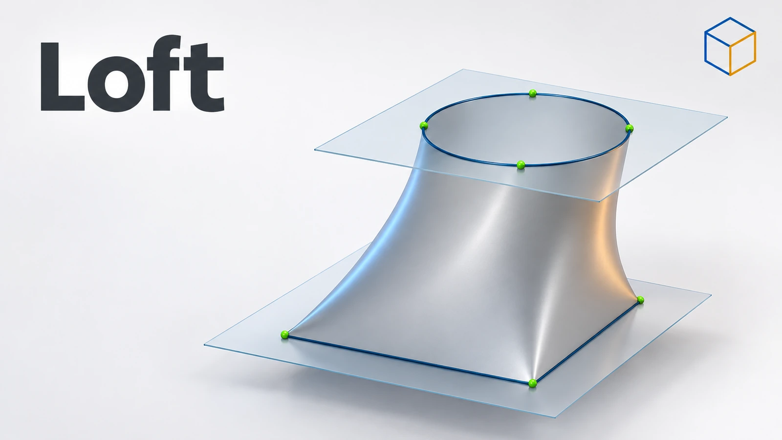
Loft blends between two or more profiles on different planes — a square base into a round top, a nozzle, a duct transition. Each profile is a closed sketch (or a face). SOLIDWORKS connects them in the order you pick. Guide curves and start/end constraints control the shape in between, and connectors fix lofts that come out twisted.
 Kevin Walsh
Where to find it
Features tab → Lofted Boss/Base; Lofted Cut
Loft options
| Option | What it does |
|---|---|
| Profiles | Two or more closed sketches, faces or edges; order with the arrows |
| Start/End Constraints | Shape at the first and last profile, e.g. Normal to Profile |
| Guide Curves | Splines or lines touching each profile that steer the shape |
| Centerline Parameters | A centerline the loft follows between profiles |
| Connectors | Which points of the profiles are joined — fixes twisting |
| Thin Feature | Hollow loft with a wall thickness |
For smooth, high-quality shapes controlled in two directions, use Boundary.
Practise it: the lofted hopper exercise.
When it twists or fails: sweep and loft errors shows how to line up connectors and profiles.
Step by step
-
1
Create the two sketches
On the Top Plane sketch a 40 × 40 Center Rectangle. Create a plane 50 mm above the Top Plane and sketch a 20 × 20 Center Rectangle on it.
-
2
Start the loft
Features → Lofted Boss/Base. In Profiles pick the two sketches — click each near the same corner, because the pick points become the connectors.
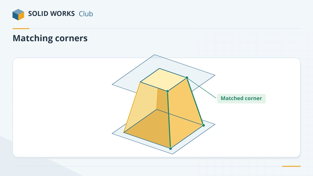
Pick both profiles near the same corner so the connectors line up. -
3
Check the preview
The preview shows a tapered block. If it looks twisted, drag the green connector dots to matching corners, or right-click → Reset connectors and pick again.
-
4
Confirm
Click the tick. Add constraints such as Normal to Profile at the start or end only if you need a curved transition.
Common mistakes
- Picking profiles at different corners, which twists the loft.
- Non-planar sketches as profiles — loft profiles must be planar (Boundary can use non-planar curves).
- Expecting tangency in the middle of a loft — loft controls tangency only at the first and last profiles.
- Open profiles for a solid loft; solids need closed profiles.
Lesson 15 of 18 in the features course.
Practice
Loft the 40 × 40 square on the Top Plane to the 20 × 20 square 50 mm above. Check: volume 46,666.67 mm³ — a square frustum, h/3 × (A1 + A2 + √(A1·A2)).
Sources
- Javelin — Creating a simple loft (Nov 2023)
- Javelin — Getting to know the loft feature (May 2025)
- GoEngineer — SOLIDWORKS lofts FAQ
- GoEngineer — Managing loft connectors (Dec 2022)
- GoEngineer — Loft vs Boundary: key differences (Sep 2024)
- Solid Solutions — How to create planes (Jul 2023)
Checked November 2026. SOLID WORKS Club is independent; menu names can differ slightly between releases.
Frequently asked questions
How many profiles does a loft need?
+
At least two. They are usually on different planes, and the loft follows the order shown in the Profiles box — use the arrows to change it.
Why is my loft twisted?
+
The connectors join different points of the profiles. Drag the green connector dots to matching points, or pick the profiles near matching corners.
Can a loft end at a point?
+
Yes, a sketch point can be the last profile, giving a pointed or domed end.
What is the difference between Loft and Boundary?
+
Boundary treats both directions equally and can control tangency and curvature at every curve, not just the ends. It usually gives smoother surfaces for complex shapes.
Related
- SOLIDWORKS Boundary Boss/BaseHow Boundary Boss/Base works in SOLIDWORKS, how it differs from Loft (Direction 1 and 2 curves, tangency and curvature at every curve), and when to choose each.
- SOLIDWORKS SweepHow to use Swept Boss/Base and Swept Cut in SOLIDWORKS: profile and path rules, Pierce, circular profiles, orientation, twist and guide curves.
- SOLIDWORKS reference planesHow to create reference planes in SOLIDWORKS: offset, angled, mid plane, tangent to a cylinder, normal to an edge, several at once, and Ctrl-drag.
- SOLIDWORKS Extruded Boss/BaseHow to use Extruded Boss/Base in SOLIDWORKS: every end condition from Blind to Mid Plane, Direction 2, draft, thin features, Selected Contours and Merge result.