Drawings · Lesson 9
Tolerances and precision in SOLIDWORKS drawings
A tolerance tells the manufacturer how far a size may vary. In SOLIDWORKS you set it on the dimension itself, in the Tolerance/Precision section of its PropertyManager: the tolerance type (for example bilateral), the upper and lower values, and the number of decimals for the value and for the tolerance. Defaults live in Document Properties, and dimension styles let you reuse settings.
 Kevin Walsh
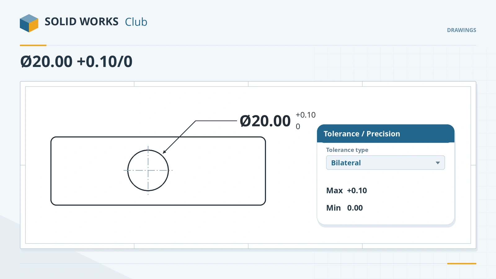
Where to find it
Select a dimension → PropertyManager → Tolerance/Precision
Where tolerance and precision are set
| Level | Where |
|---|---|
| One dimension | PropertyManager → Tolerance/Precision, or the dimension palette |
| Document default | Document Properties → Dimensions → Primary precision |
| Reusable | Dimension styles (.sldstl): add, save and load |
| Template | Defaults saved in the drawing template |
| Holes | Hole Wizard Type tab → Tolerance/Precision (2019+) |
The precision dialog sets decimals separately for primary, dual and angular values, for the value and for the tolerance. Leading and trailing zero display is set in Document Properties. Form and position tolerances use GD&T. Tolerances on 3D annotations can drive machining strategies in SOLIDWORKS CAM.
Step by step
-
1
Select the hole dimension
On the plate drawing, click the Ø20 dimension.
-
2
Choose a tolerance type
In Tolerance/Precision pick Bilateral from the tolerance type list, enter +0.10 as the upper and 0.00 as the lower value.
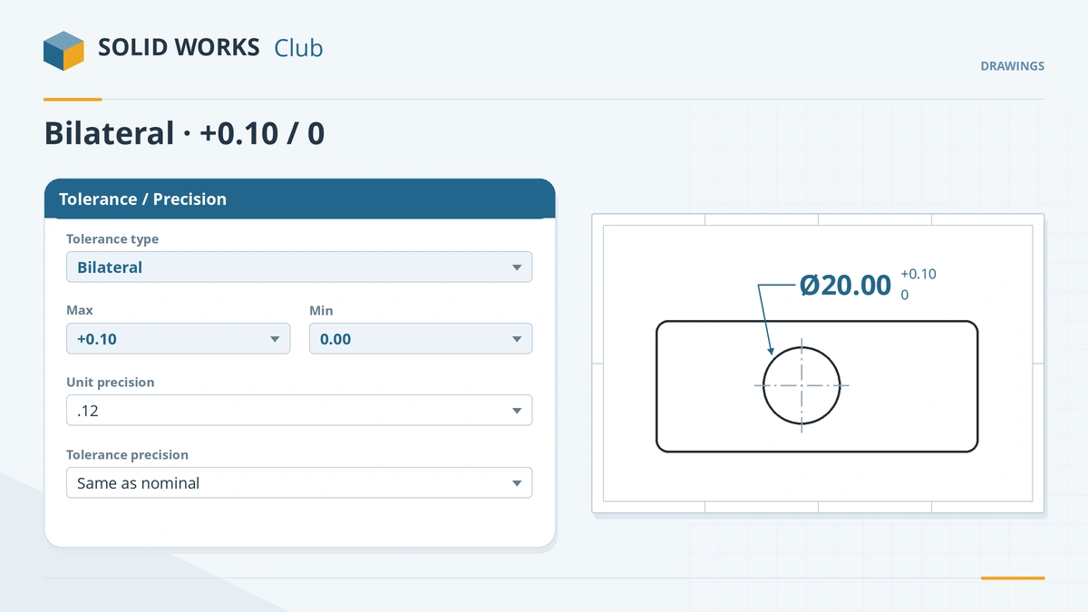
Choose the tolerance type, enter the limits, set the decimals. -
3
Set precision
Set the value precision to .12 (two decimals) and the tolerance precision to Same as nominal. The dimension now reads Ø20.00 with +0.10 / 0.
-
4
Save it as a style
With the dimension selected, use Add or Update a Style in the PropertyManager to save these settings for reuse.
Common mistakes
- Overriding precision on single dimensions, then changing Document Properties and wondering why some do not follow. Set overridden dimensions back to *Document* precision.
- Tolerances so tight they cannot be made — ask your machinist what the process holds.
- Forgetting a general tolerance note for dimensions without their own tolerance.
Lesson 9 of 14 in the drawings course.
Practice
Give the Ø20 hole a bilateral tolerance of +0.10 / 0 with two decimals. Check: the dimension shows Ø20.00 with +0.10 and 0 stacked beside it, and Model Items in a new drawing view imports the tolerance because it is stored in the model.
Sources
- Javelin — Drawing dimension precision troubleshooting (Jul 2023)
- SOLIDWORKS Help 2024 — Precision dialog
- Hawk Ridge — Putting style into dimensions
- Javelin — Hole Wizard tolerances (2019)
- Javelin — How to dimension holes (Apr 2026)
- GoEngineer — Inserting model dimensions into a drawing
Checked November 2026. SOLID WORKS Club is independent; menu names can differ slightly between releases.
Frequently asked questions
How do I add a tolerance to a dimension in SOLIDWORKS?
+
Select the dimension and open Tolerance/Precision in the PropertyManager. Choose the tolerance type, enter the values and set the precision.
How do I change the number of decimals?
+
Set the precision in the dimension's PropertyManager, or change the default under Document Properties → Dimensions → Primary precision.
Can Hole Wizard holes carry tolerances?
+
Yes. Since SOLIDWORKS 2019 the Hole Wizard Type tab has Tolerance/ Precision settings, and the values appear in the hole callout.
Where do tolerances on drawings come from?
+
Tolerances added to model dimensions travel to the drawing with Model Items; tolerances added in the drawing stay in the drawing.
Related
- Dimensions in SOLIDWORKS drawingsHow to dimension SOLIDWORKS drawings: import Model Items, add reference dimensions, ordinate and chain dimensions, hole callouts and auto arrange.
- GD&T in SOLIDWORKS drawingsHow to add GD&T in SOLIDWORKS drawings: datum feature symbols, the Geometric Tolerance builder, datum targets, drafting standards and DimXpert/MBD.
- SOLIDWORKS Hole WizardHow to use the SOLIDWORKS Hole Wizard: hole types, standards, sizes and fit, the Type and Positions tabs, cosmetic threads, slots, favourites and Advanced Hole.
- How to change units in SOLIDWORKSChange units in SOLIDWORKS from the status bar or Document Properties: MMGS, IPS, MKS, CGS or custom. Set decimals, dual dimensions and default units.