Drawings · Lesson 2
SOLIDWORKS drawing views
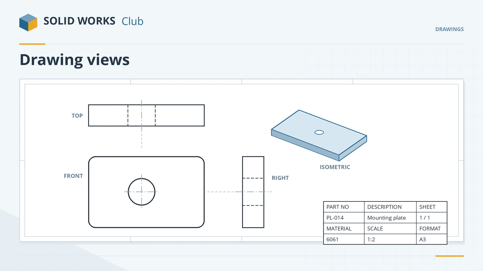
Most drawings start with one model view — usually the front — and projected views folded from it. Projected views stay aligned to their parent, so a top view only moves up and down. Standard 3 View places front, top and side in one click. Each view has its own scale, display style and tangent-edge setting.
 Kevin Walsh
Where to find it
View Layout tab (Drawing tab in some layouts) → Model View, Projected View, Standard 3 View
View types in this course
| View | Created from | Lesson |
|---|---|---|
| Model View | The model, in a chosen orientation | This lesson |
| Projected View | A parent view, folded 90° | This lesson |
| Standard 3 View | The model — front, top and side at once | This lesson |
| Section View | A cutting line on a parent view | Section view |
| Detail View | A circle or profile on a parent view | Detail view |
| Broken-out Section | A closed sketch on an existing view | Broken-out section |
| Auxiliary View | A reference edge | Auxiliary view |
Display styles
Each view can be wireframe, hidden lines visible, hidden lines removed, shaded with edges or shaded. Mixed styles inside one view are done with display states. Tangent edges can be visible, shown with a phantom font, or removed.
Step by step
-
1
Insert a model view
On a new sheet, View Layout → Model View, pick the plate, choose the Front orientation and click to place it.
-
2
Project views from it
Projected View, click the front view, move up and click — a top view. Do the same to the right for a right view, and diagonally for an isometric view.
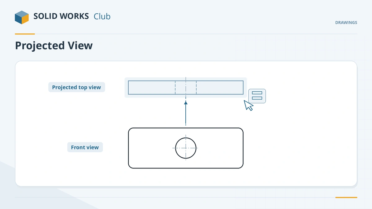
Projected views fold from the parent and stay aligned with it. -
3
Set display styles
Select the front view and set Display style to Hidden lines visible so the hole shows as dashed lines in the side views. Set the isometric to Shaded with edges.
-
4
Move a view
Drag a view by its border, or hold Alt and drag anywhere inside it. Moving the front view moves its aligned children too.
Common mistakes
- Breaking alignment by accident and losing the projection relationship. Use Tools → Align Drawing View → Default Alignment to restore it.
- Tangent edges cluttering views. Right-click the view → Tangent Edge → Tangent Edges with Font (phantom) or Removed.
- Hiding a view and leaving a large X marker on screen — turn it off under View → Hide/Show → Hidden Views.
Lesson 2 of 14 in the drawings course.
Practice
Place a front view of the plate and project a top, right and isometric view, with hidden lines visible in the orthographic views. Check: the side views show the Ø20 hole as two dashed lines 20 mm apart (measure with Smart Dimension), and the top view moves only vertically when dragged.
Sources
- Javelin — Complete guide to drawing views (Sep 2026)
- CATI — Projected drawing views
- Hawk Ridge — Align drawing entities
- CATI — Creating and navigating drawings
- Hawk Ridge — Hidden drawing view marker
- GoEngineer — Mixed display styles in drawings
- Javelin — Shaded with edges and tangent edges
- Javelin — Non-standard drawing views (Aug 2026)
- Javelin — Best practices for the View Palette (Sep 2025)
Checked November 2026. SOLID WORKS Club is independent; menu names can differ slightly between releases.
Frequently asked questions
How do I add a projected view in SOLIDWORKS?
+
Click Projected View, select the parent view, move the pointer in the direction of the new view and click to place it.
How do I break alignment of a drawing view?
+
Right-click the view → Alignment → Break Alignment, or use Tools → Align Drawing View. Default Alignment restores it.
How do I show hidden lines in a drawing view?
+
Select the view and set Display style to Hidden lines visible in the PropertyManager or on the heads-up toolbar.
How do I insert a view in a non-standard orientation?
+
Orient the model as you want, then use the View Palette's Current view option, or save a named view in the part and insert it.
Related
- SOLIDWORKS section viewsHow to create section views in SOLIDWORKS drawings: Section View Assist, horizontal, vertical, aligned and offset cuts, half sections, Section Scope and depth.
- Auxiliary, crop and alternate position viewsHow to create auxiliary views of angled faces in SOLIDWORKS drawings, crop views to the area you need, and show moving parts with alternate position views.
- SOLIDWORKS drawing basicsSOLIDWORKS drawing basics: make a drawing from a part, pick the template and sheet, place views from the View Palette, set scale, projection, Detailing mode.
- Dimensions in SOLIDWORKS drawingsHow to dimension SOLIDWORKS drawings: import Model Items, add reference dimensions, ordinate and chain dimensions, hole callouts and auto arrange.