Drawings · Lesson 3
SOLIDWORKS section views
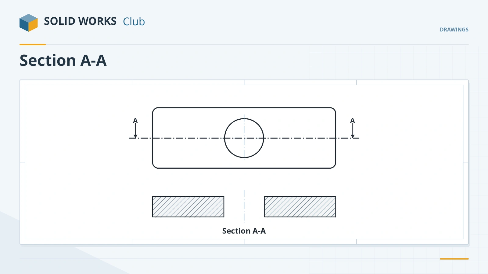
A section view shows the inside of a part as if it were cut along a line. Since SOLIDWORKS 2013 the Section View tool places the cutting line for you: horizontal, vertical, auxiliary or aligned, with arc, single and notch offsets to step through several features. Cut faces are hatched; ribs and fasteners can be excluded from the cut, as drafting standards expect.
 Kevin Walsh
Where to find it
View Layout tab → Section View
Section view options
| Option | What it does |
|---|---|
| Cutting line | Vertical, horizontal, auxiliary or aligned |
| Offsets | Arc, single and notch offsets, combinable |
| Half section | Cuts half the part (since 2013, command first) |
| Auto flip | Arrows follow where you place the view |
| Section Scope | Exclude components, ribs, fasteners; Toolbox parts are fasteners by default |
| Auto hatching | Changes hatch angle between adjacent cut faces |
| Section depth / Slice | Show only material up to a depth, or only the cut faces |
| Emphasized outline (2017+) | Thick outline around cut faces |
Section views are a CSWA drafting topic — see the CSWA guide.
Step by step
-
1
Start a horizontal section
On the plate drawing, Section View. Choose the Horizontal cutting line and click the centre of the hole in the front view.
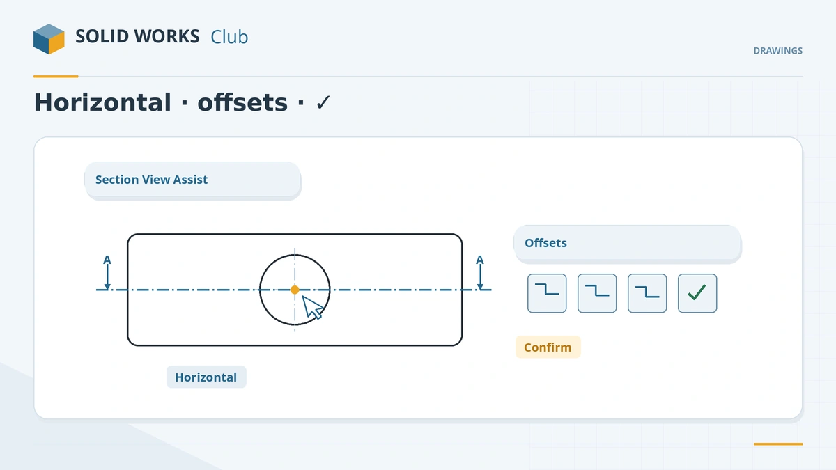
Pick the line type, click a point, then add offsets or confirm. -
2
Confirm the line
Click the green tick on the pop-up toolbar (or add offsets first — arc, single or notch — to step the line through other features).
-
3
Place the view
Move the pointer below the front view and click. The view is labelled Section A-A. Tick Auto flip if the arrows should follow the side you place the view on.
-
4
Check the hatching
The cut faces are hatched; the hole appears as a gap. For assemblies, the Section Scope tab lets you exclude components, ribs and fasteners.
Common mistakes
- A cutting line not tied to geometry. After a model change it may miss the feature. Edit the section line sketch and add relations.
- Hatching fasteners and shafts in assembly sections. Exclude fasteners in Section Scope (Toolbox parts count as fasteners).
- Section views that show everything behind the cut. Use Section Depth or Slice to show only what matters.
Lesson 3 of 14 in the drawings course.
Practice
Cut the plate's front view horizontally through the hole centre and place Section A-A below it. Check: the section shows two hatched rectangles, each 40 × 20 mm, with a 20 mm gap for the hole.
Sources
- SOLIDWORKS blog — Section View Assist (2013)
- SOLIDWORKS Help 2024 — Section views in drawings
- SOLIDWORKS Help 2024 — Section view offset examples
- Javelin — Section jog line (2017)
- GoEngineer — Section Scope in drawings (Sep 2026)
- Javelin — Automatically exclude components from section views (2021)
- GoEngineer — Section depth in drawings (2022)
- Hawk Ridge — Removed section views (2019)
- Javelin — Emphasized outline section view (2017)
- Javelin — Section auto flip and projection (2017)
- Javelin — Detail and section views with intelligence (Feb 2026)
Checked November 2026. SOLID WORKS Club is independent; menu names can differ slightly between releases.
Frequently asked questions
How do I make an offset section view?
+
Place the cutting line with Section View, then add arc, single or notch offsets from the pop-up toolbar before confirming. You can also sketch a jogged line yourself.
How do I make a half section?
+
Section View includes half-section options: choose the half-section shape and click the centre point. No sketch is needed (since 2013).
How do I exclude ribs or fasteners from a section?
+
Use the Section Scope tab when creating the view, or later in the view's properties. Parts with an IsFastener = 1 property are treated as fasteners.
What is a removed section?
+
A section placed away from the parent view, with its own command since SOLIDWORKS 2019.
Related
- SOLIDWORKS detail viewsHow to create detail views in SOLIDWORKS drawings: circle or profile outline, scale, label, detail styles like connected or broken circle, jagged outline.
- Broken-out sections and break viewsHow to use broken-out sections in SOLIDWORKS drawings to reveal hidden features, set the depth, and shorten long parts with a break view and break gap.
- SOLIDWORKS drawing viewsHow to place SOLIDWORKS drawing views: Model View, Standard 3 View and projected views, alignment, display styles, tangent edges, moving and hiding views.
- CSWA exam guide: format, cost and how to prepareThe CSWA (SOLIDWORKS Design Associate) exam in 2026 — $99, 3 hours, 70% to pass, online with your own SOLIDWORKS. Sections, rules and a study plan.