Advanced parts · Lesson 5
SOLIDWORKS coordinate systems
A coordinate system is a reference with its own origin and X, Y, Z directions. You need one when results must be measured from somewhere other than the part origin — centre of mass from a mounting point, an export for a machine or another CAD system, or a table driven pattern. Exam questions often define their own coordinate system for exactly this reason.
 Kevin Walsh
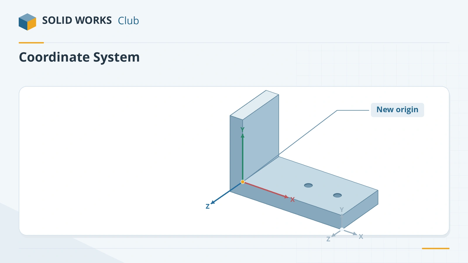
Where to find it
Features tab → Reference Geometry → Coordinate System
Where coordinate systems are used
| Use | Where you choose it |
|---|---|
| Centre of mass, inertia | Mass Properties → output coordinate system |
| Export | Save As → Options (STEP, Parasolid, IGES) |
| Table driven pattern | Pattern PropertyManager |
| Mates and Simulation remote loads | Selection in the respective tool |
| Bounding box (2026+) | Bounding box options |
Show or hide coordinate systems from Hide/Show Items on the heads-up toolbar.
Step by step
-
1
Build the L-bracket
Use the L-bracket from the Mass Properties lesson: base 80 × 10 mm, wall 10 × 60 mm, extruded Mid Plane 40 mm, outer corner on the origin.
-
2
Create the coordinate system
Add a reference point at the midpoint of the inner corner edge (where the base meets the wall on the inside). Then Reference Geometry → Coordinate System: Origin = that point, X axis = an edge along the base, Y axis = an edge up the wall. Flip the axes if they point the wrong way.
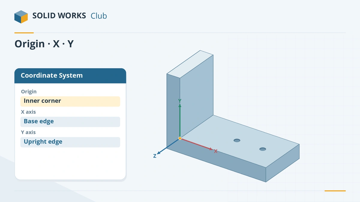
Origin at the inner corner, X along the base, Y up the wall. -
3
Report mass properties in it
Evaluate → Mass Properties, choose the new coordinate system as the output coordinate system. The centre of mass is now measured from the inner corner.
-
4
Export with it
File → Save As → STEP, open Options and select the coordinate system as the output coordinate system — the receiving system sees your chosen origin.
Common mistakes
- Axes pointing the opposite way from what the question expects — the coordinates change sign. Flip the axis.
- Building the coordinate system on geometry that changes later; the origin moves with it.
- Reading the bottom inertia matrix as if it were at the centre of mass — it is taken at the output coordinate system.
Lesson 5 of 16 in the advanced parts course.
Practice
Place a coordinate system at the inner corner of the L-bracket, in the middle of its width (on the Front Plane), with X along the base and Y up the wall. Check: Mass Properties in that coordinate system reports the centre of mass at X = 16.54 mm, Y = 6.54 mm, Z = 0 — 10 mm less in X and Y than from the part origin.
Sources
- Javelin — Generating a custom coordinate system (2018)
- CADimensions — Exporting with a user-defined coordinate system
- GoEngineer — Mass moments of inertia explained (Mar 2025)
- SOLIDWORKS Tech Blog — Basics of reference geometry (2018)
- GoEngineer — SOLIDWORKS 2026 parts and features (Oct 2025)
- CATI — Table driven and other patterns (Jan 2022)
Checked November 2026. SOLID WORKS Club is independent; menu names can differ slightly between releases.
Frequently asked questions
How do I create a coordinate system in SOLIDWORKS?
+
Reference Geometry → Coordinate System. Pick a vertex or point for the origin, then edges, faces or axes for the X, Y and Z directions; flip them as needed.
How do I get centre of mass relative to a point?
+
Create a coordinate system at that point and choose it as the output coordinate system in the Mass Properties dialog.
How do I export a STEP file with a different origin?
+
In Save As, open Options for the format and choose your coordinate system as the output coordinate system.
What is new for coordinate systems in SOLIDWORKS 2026?
+
Bounding boxes can be defined by a coordinate system's axes, and reference points can be placed by typing X, Y, Z values.
Related
- SOLIDWORKS Mass PropertiesHow to use Mass Properties in SOLIDWORKS: mass, volume, centre of mass and inertia, units, coordinate systems, overrides, Measure and Section Properties.
- SOLIDWORKS reference axis and temporary axesHow to create a reference axis in SOLIDWORKS, show temporary axes, and use axes for revolves and angled planes, plus points and coordinate systems.
- How to export SOLIDWORKS to STEPHow to save a SOLIDWORKS part or assembly as STEP, which AP version to choose (AP203, AP214, AP242), exporting components separately, and pitfalls.
- Curve, sketch, table, fill and variable patternsSOLIDWORKS curve driven, sketch driven, table driven, fill and variable patterns explained: what each does, when to use it, and a fill pattern example.