Advanced parts · Lesson 3
Curve, sketch, table, fill and variable patterns
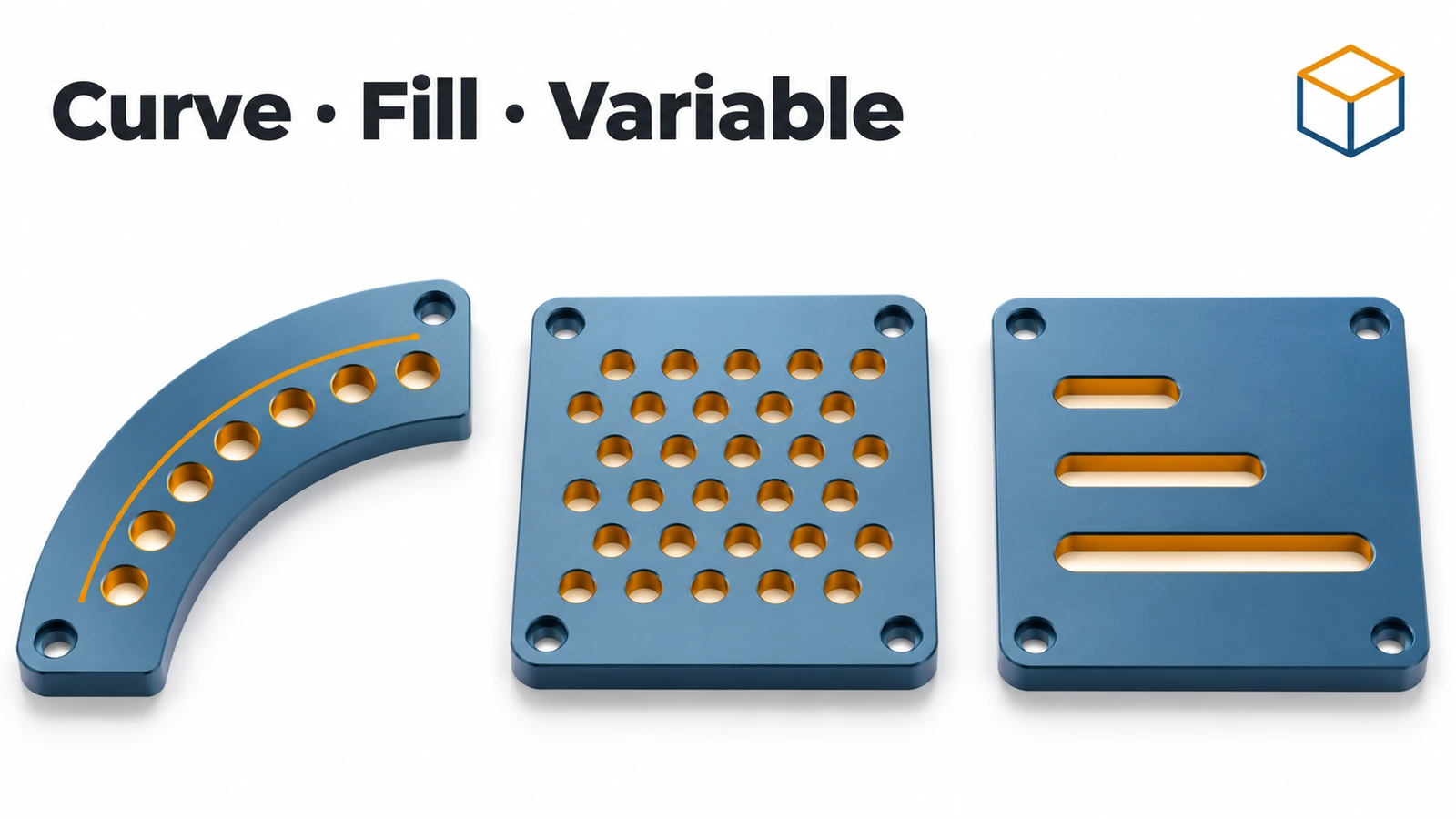
Not every repetition is a row or a circle. SOLIDWORKS has five more pattern tools: Curve Driven follows a curve or edge; Sketch Driven puts a copy on every sketch point; Table Driven uses X-Y coordinates; Fill Pattern fills a face with perforations; and Variable Pattern, added in 2015, lets each copy have different dimensions from a table.
 Kevin Walsh
Where to find it
Features tab → Linear Pattern flyout (Insert → Pattern/Mirror)
Which pattern to use
| Pattern | Copies are placed… | Use for |
|---|---|---|
| Curve Driven | Along a curve, edge, helix or 3D sketch | Holes along curved edges, grooves along a path |
| Sketch Driven | At each sketch point | Irregular hole layouts |
| Table Driven | At X-Y coordinates from a table (needs a coordinate system) | Layouts from external data |
| Fill | Across a face, in Perforation, Circular, Square or Polygon layouts | Vents, grilles, perforated panels |
| Variable (2015+) | Per-instance values in a table | Copies of different sizes |
For regular rows and circles, Linear and Circular Pattern are simpler and faster. Table-driven patterns need a coordinate system.
Step by step
-
1
Make a plate
Extrude a 100 × 60 mm rectangle 3 mm — a thin cover.
-
2
Start a Fill Pattern
Insert → Pattern/Mirror → Fill Pattern. Fill boundary: the top face. Layout: Perforation. Instance spacing 10 mm, margin 8 mm.
-
3
Use a predefined cut
Under Features to Pattern choose Create seed cut, shape Circle, diameter 5 mm. No seed feature is needed.
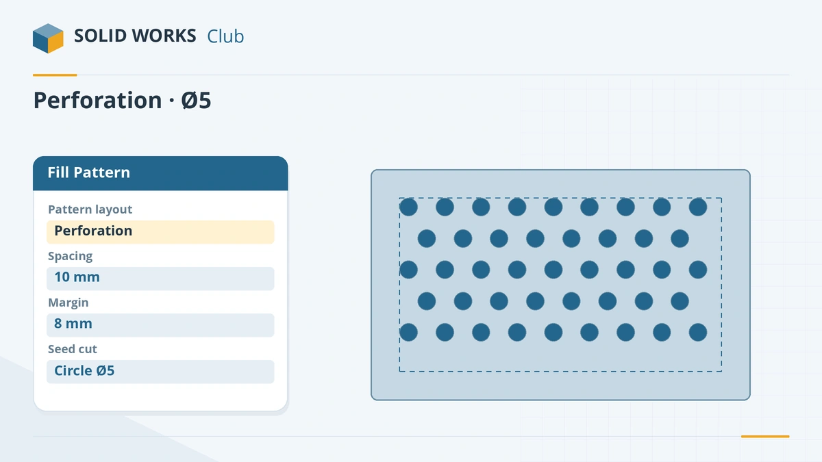
Fill Pattern can create its own seed cut — no feature needed. -
4
Confirm and adjust
Click the tick. Change the margin or spacing to see how the number of holes changes; a negative margin lets holes overhang the edge.
Common mistakes
- Curve driven patterns stopping at corners — use a composite curve so the path is one curve.
- Sketch driven patterns whose sketch is later edited carelessly — every sketch point is a copy.
- Variable Pattern tables that repeat the seed position as instance 1 — instance 0 is already the seed.
Lesson 3 of 16 in the advanced parts course.
Practice
Fill the top face of a 100 × 60 × 3 mm plate with a Perforation layout of Ø5 holes at 10 mm spacing and an 8 mm margin. Check: count the instances in the PropertyManager or by hiding the plate — then change the spacing to 12 mm and see the count fall. This pattern has no fixed answer: the count depends on the layout settings.
Sources
- CATI — Curve driven pattern
- GoEngineer — 5 advanced patterning techniques (Mar 2026)
- CATI — Sketch driven pattern
- CATI — Table driven and other patterns (Jan 2022)
- GoEngineer — Fill pattern tool explained (Oct 2022)
- Javelin — Variable pattern (2015+)
- GoEngineer — Variable pattern tool explained (Apr 2022)
- Javelin — How to use patterns in SOLIDWORKS (Jun 2026)
Checked November 2026. SOLID WORKS Club is independent; menu names can differ slightly between releases.
Frequently asked questions
What is a curve driven pattern?
+
A pattern that places copies along a curve, edge, helix, 3D sketch or other path. Use a composite curve for paths with corners.
What is a sketch driven pattern?
+
A pattern that places a copy of the seed at each point of a sketch — useful when holes have no regular spacing.
What is a fill pattern used for?
+
Filling a face with holes or features, such as perforations, vents and speaker grilles, using layouts like Perforation, Circular, Square or Polygon.
What is a variable pattern?
+
A pattern introduced in SOLIDWORKS 2015 where each instance can have different dimension values, set in a pattern table.
Related
- SOLIDWORKS Linear PatternHow to use Linear Pattern in SOLIDWORKS: one or two directions, spacing, Up to reference, skipping and varying instances, and Geometry pattern.
- SOLIDWORKS Circular PatternHow to use Circular Pattern in SOLIDWORKS: pattern axis, equal spacing, angle and instances, symmetric Direction 2, skipping instances and preview options.
- SOLIDWORKS coordinate systemsHow to create a coordinate system in SOLIDWORKS and use it for mass properties, centre of mass, STEP or Parasolid export and table driven patterns.
- 3D sketches in SOLIDWORKSHow to draw a 3D sketch in SOLIDWORKS: start it, switch planes with Tab, use the space handle and Along X/Y/Z relations, and build sweep paths.