Project 11
How to design a 3D-printed enclosure in SOLIDWORKS
An enclosure for a small electronics board is the most common thing people design for a 3D printer. The rules come from the process: walls thick enough to print, clearance so parts fit, no unsupported overhangs past about 45°, and an export the slicer reads well. This project builds a two-part box with a lid that locates on a lip.
 Kevin Walsh
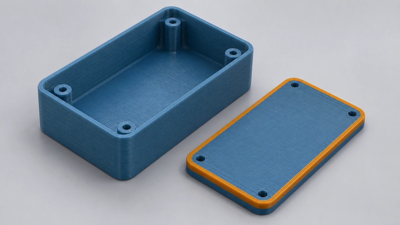
- Level
- Project
- Time
- 45 min
- Material
- PLA (print)
Specification
| Parameter | Value |
|---|---|
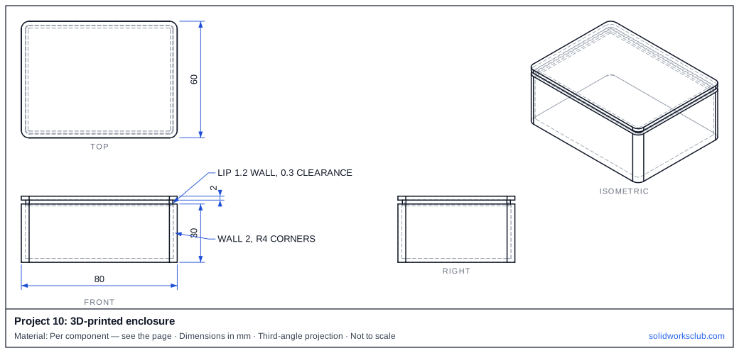
| Base outside | 80 × 60 × 30 mm, R4 corners |
| Wall | 2 mm (shell) |
| Lid | 2 mm with a 3 mm locating lip |
| Lip clearance | 0.3 mm per side |
| Export | STL (binary) or 3MF |
The drawing
Step by step
1. Base
Extrude 80 × 60 × 30, fillet the vertical edges R4, shell 2 mm with the top open.
2. Lid
A 2 mm plate with the same outline, plus a 1.2 mm thick lip that fits inside the base with 0.3 mm clearance per side.
3. Snap fits (optional)
Cantilever clips at least 5 mm wide, tapered toward the tip, with a root fillet of half the thickness; don't print them standing in Z.
4. Check printability
Print3D (File → Print3D) flags thin walls and faces needing support for your printer.
5. Export
Save as STL with Fine resolution and binary format, or 3MF to keep colours. Set the same units in the slicer — STL has none.
Check your result
- Base outside 80 × 60 × 30 mm.
- Total printed volume 35,005.70 mm³ — multiply by your filament's density for weight.
Compare your model with the STEP file above — it opens in SOLIDWORKS and most other CAD programs.
Next: project 12 — sheet metal box.
Download files
Commands used
Show solution
- Base. Extrude 80 × 60 × 30, fillet the vertical edges R4, shell 2 mm with the top open.
- Lid. A 2 mm plate with the same outline, plus a 1.2 mm thick lip that fits inside the base with 0.3 mm clearance per side.
- Snap fits (optional). Cantilever clips at least 5 mm wide, tapered toward the tip, with a root fillet of half the thickness; don't print them standing in Z.
- Check printability. Print3D (File → Print3D) flags thin walls and faces needing support for your printer.
- Export. Save as STL with Fine resolution and binary format, or 3MF to keep colours. Set the same units in the slicer — STL has none.
Sources
- CATI — STL output settings for CAD (May 2015)
- GoEngineer — Save an assembly as an STL file (May 2022)
- SOLIDWORKS Tech Blog — Preparing a model for 3D printing (Aug 2018)
- Javelin — Importing and exporting 3MF (Oct 2016)
- Javelin — Optimize 3D printing with Print3D (Jan 2022)
- Xometry Pro — Quick design guide for FDM
- FacFox — How to design parts for FDM 3D printing
- Prusa Research — Modeling with 3D printing in mind
- Protolabs Network (Hubs) — Designing snap-fit joints for 3D printing
- Formlabs — Designing 3D printed snap-fit enclosures
- Fictiv — How to design snap fit components (Oct 2025)
Checked November 2026. SOLID WORKS Club is independent; menu names can differ slightly between releases.
Frequently asked questions
How much clearance for 3D-printed parts that fit together?
+
Start at about 0.3 mm for FDM; one service gives at least 0.5 mm for moving parts. Test-print a corner first.
STL or 3MF?
+
3MF (SOLIDWORKS 2017 and later) keeps colours and materials and makes smaller files; STL is universal.
Related
- How to make a sheet metal box in SOLIDWORKSMake a sheet metal box in SOLIDWORKS: base flange, four edge flanges, closed corners, flat pattern and DXF, with the blank size checked by K-factor.
- How to model a bench vise in SOLIDWORKSModel a bench vise assembly in SOLIDWORKS: body, moving jaw, lead screw and handle, a screw mate for travel and a limit distance mate for the opening.
- SOLIDWORKS ShellHow to use Shell in SOLIDWORKS to hollow a part: faces to remove, wall thickness, shell outward, multi-thickness walls, and what to do when the shell fails.
- Intermediate SOLIDWORKS exercises19 intermediate SOLIDWORKS exercises: sweeps, lofts, shells, draft, Hole Wizard and three small assemblies, each with a drawing, STEP file and check mass.