Project 13
How to design a simple gearbox in SOLIDWORKS
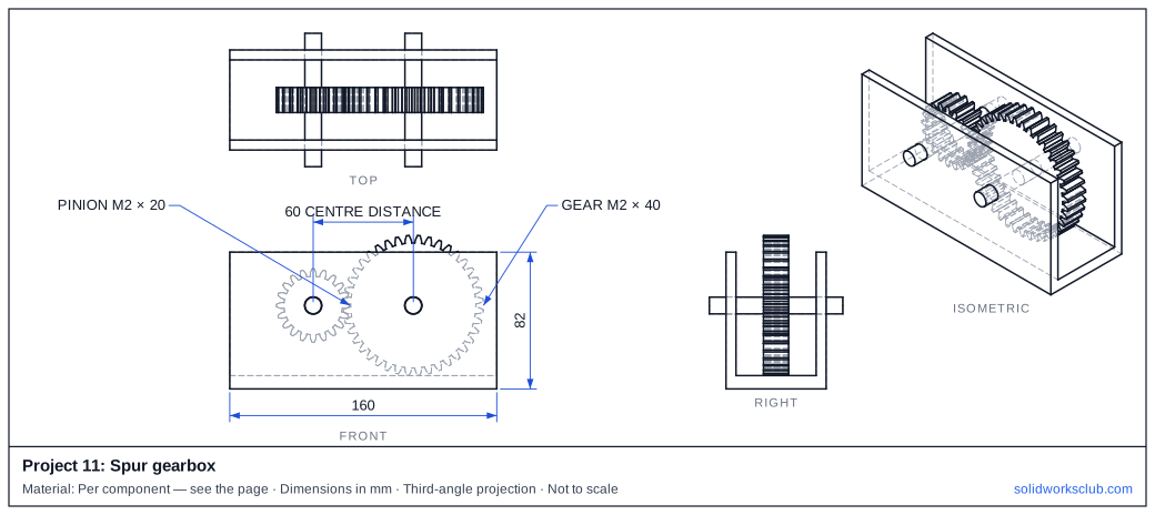
A gearbox ties together gears, shafts, a housing and mates. The key number is the centre distance: for standard spur gears a = m(z1 + z2)/2, so module 2 gears with 20 and 40 teeth sit 60 mm apart and give a 2:1 reduction. The gear mate drives the motion; Interference Detection checks the fit — the mate itself does not.
 Kevin Walsh
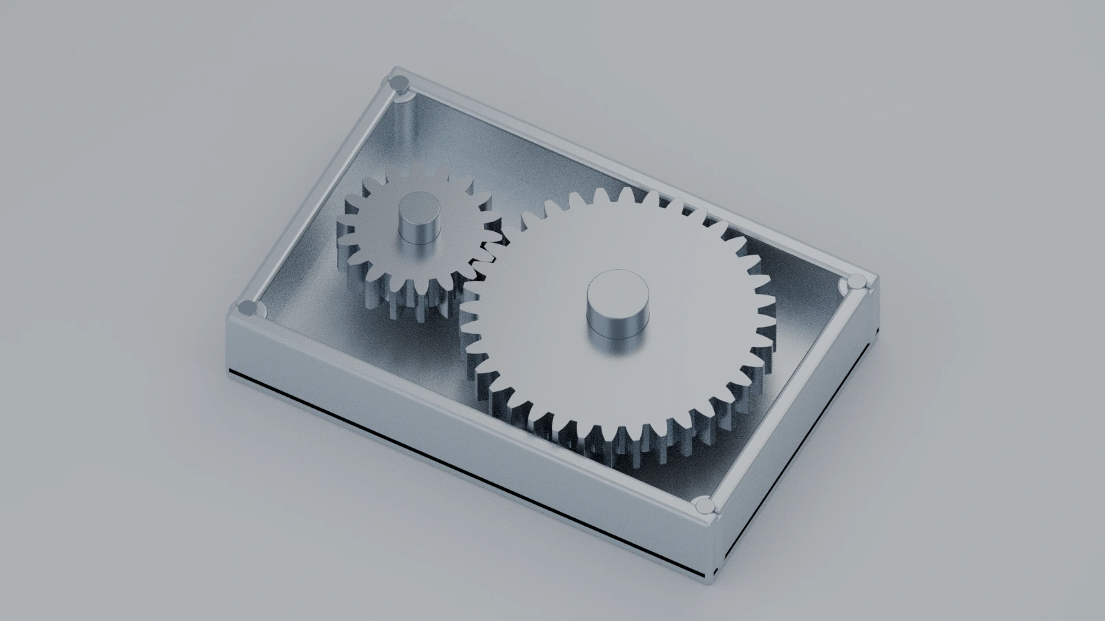
- Level
- Project
- Time
- 60 min
- Material
- Per component (see the check)
- Check mass
- 1,396.71 g total
Specification
| Parameter | Value |
|---|---|
| Module | 2 mm |
| Pinion / gear teeth | 20 / 40 |
| Ratio | 2:1 |
| Centre distance m(z1 + z2)/2 | 60 mm |
| Face width | 15 mm |
| Shafts | Ø10, through both side walls |
The drawing
Step by step
1. Housing
Base 160 × 60 × 8 and two side walls; bore Ø10.4 holes 60 mm apart at the shaft height.
2. Gears
Use the spur gear project or Toolbox gears with module 2 and 20 / 40 teeth; Ø10 bores.
3. Assemble
Shafts concentric with the housing holes, gears concentric with the shafts and coincident on their mid-planes. Rotate one gear so the teeth mesh.
4. Gear mate
Mechanical mates → Gear: select the two gears' pitch or bore faces, set the ratio 20:40 (tooth counts) and Reverse if needed.
5. Check
Interference Detection lists any overlap with its volume; Physical Dynamics shows backlash a gear mate hides.
Check your result
- Centre distance 60 mm.
- One input turn gives half an output turn.
- Our STEP assembly weighs 1,396.71 g (585.47 g aluminium + 811.24 g mild steel) (housing aluminium 2.70 g/cm³, gears and shafts mild steel 7.85 g/cm³).
Compare your model with the STEP file above — it opens in SOLIDWORKS and most other CAD programs.
Next: project 14 — robot arm.
Download files
Commands used
Show solution
- Housing. Base 160 × 60 × 8 and two side walls; bore Ø10.4 holes 60 mm apart at the shaft height.
- Gears. Use the spur gear project or Toolbox gears with module 2 and 20 / 40 teeth; Ø10 bores.
- Assemble. Shafts concentric with the housing holes, gears concentric with the shafts and coincident on their mid-planes. Rotate one gear so the teeth mesh.
- Gear mate. Mechanical mates → Gear: select the two gears' pitch or bore faces, set the ratio 20:40 (tooth counts) and Reverse if needed.
- Check. Interference Detection lists any overlap with its volume; Physical Dynamics shows backlash a gear mate hides.
Sources
- CATI — Gear mate galore (Mar 2018)
- GoEngineer — Worm gear mate quick tip (Jun 2026)
- SolidProfessor — Mechanical assembly mates in SOLIDWORKS 2019 (Jan 2019)
- GoEngineer — Toolbox gears: kinetic art project, part II (Apr 2020)
- CATI — Assembly validation tools: interference detection (Jul 2014)
- Javelin — How to use Move Component (Mar 2026)
- KHK USA — Standards in terminology for gearing (PDF)
- Hawk Ridge — Is the Toolbox spur gear a good fit? (Jul 2024)
Checked November 2026. SOLID WORKS Club is independent; menu names can differ slightly between releases.
Frequently asked questions
How do I calculate gear centre distance?
+
For standard spur gears a = m(z1 + z2)/2 — here 2 × (20 + 40)/2 = 60 mm.
Does the gear mate stop teeth from overlapping?
+
No. It only couples rotation by the ratio; check with Collision or Interference Detection.
Related
- How to design a robot arm in SOLIDWORKSDesign a simple robot arm in SOLIDWORKS: base, turret, two links and a gripper, hinge and limit angle mates, collision checks and a motion study for torque.
- How to make a sheet metal box in SOLIDWORKSMake a sheet metal box in SOLIDWORKS: base flange, four edge flanges, closed corners, flat pattern and DXF, with the blank size checked by K-factor.
- SOLIDWORKS mechanical matesHow to use SOLIDWORKS mechanical mates: Cam, Slot, Hinge, Gear, Rack and Pinion, Screw and Universal Joint, with ratios and how they simulate mechanisms.
- Intermediate SOLIDWORKS exercises19 intermediate SOLIDWORKS exercises: sweeps, lofts, shells, draft, Hole Wizard and three small assemblies, each with a drawing, STEP file and check mass.