Project 14
How to design a robot arm in SOLIDWORKS
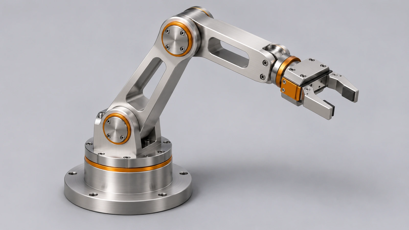
A robot arm is an assembly that moves: a base, a turret that turns, two links and a gripper. Hinge mates make the joints, limit angle mates keep them inside their range, and a motion study turns it into data — Motion Analysis can report the torque each joint motor needs.
 Kevin Walsh
- Level
- Project
- Time
- 90 min
- Material
- Aluminium, 2.70 g/cm³
- Check mass
- 1,254.45 g total
Specification
| Parameter | Value |
|---|---|
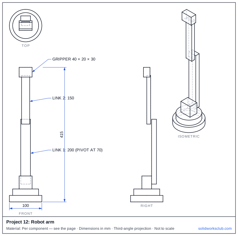
| Base / turret | Ø100 × 20 / Ø80 × 20 plus a 40 × 30 × 40 block |
| Link 1 | 200 mm, pivot 70 mm above the floor |
| Link 2 | 150 mm |
| Gripper | 40 × 20 × 30 |
| Material | Aluminium 2.70 g/cm³ |
| Height (straight up) | 415 mm |
The drawing
Step by step
1. Parts
Model each link as its own part with pivot holes at the ends.
2. Hinge mates
One hinge mate per joint: the turret on the base axis, link 1 on the turret, link 2 on link 1.
3. Limit the joints
Limit angle mates (Advanced Mates) between the links — for example −100° to 100°; use Move Component with Collision Detection to find the real limits first.
4. Motion study
Rotary motors on each joint; Motion Analysis (Premium or Simulation) plots motor torque and power.
5. Check
Drag the arm through its range with Collision Detection on.
Check your result
- Height with the arm straight up: 415 mm.
- Our STEP assembly weighs 1,254.45 g in aluminium.
Compare your model with the STEP file above — it opens in SOLIDWORKS and most other CAD programs.
Next: all exercises.
Download files
Commands used
Show solution
- Parts. Model each link as its own part with pivot holes at the ends.
- Hinge mates. One hinge mate per joint: the turret on the base axis, link 1 on the turret, link 2 on link 1.
- Limit the joints. Limit angle mates (Advanced Mates) between the links — for example −100° to 100°; use Move Component with Collision Detection to find the real limits first.
- Motion study. Rotary motors on each joint; Motion Analysis (Premium or Simulation) plots motor torque and power.
- Check. Drag the arm through its range with Collision Detection on.
Sources
- SolidProfessor — Mechanical assembly mates in SOLIDWORKS 2019 (Jan 2019)
- Hawk Ridge — Limit your angles, not your designs (Oct 2016)
- Javelin — Angle limit mates to replicate collision detection (Aug 2025)
- Javelin — Mate Controller negative values for limit angle mates (Mar 2019)
- Solid Solutions — Robotics using SOLIDWORKS Motion (May 2014)
- Javelin — How to use Move Component (Mar 2026)
- Javelin — Motion simulation in SOLIDWORKS (Feb 2018)
- Engineers Rule — Motion studies and how to do them (Dec 2016)
Checked November 2026. SOLID WORKS Club is independent; menu names can differ slightly between releases.
Frequently asked questions
How do I limit a joint's rotation?
+
Add a Limit Angle mate under Advanced Mates; since SOLIDWORKS 2019 the Mate Controller also accepts negative limits.
How do I find the motor torque?
+
Run a Motion Analysis study with rotary motors and plot the motor torque; it needs SOLIDWORKS Premium or a Simulation package.
Related
- SOLIDWORKS practice exercisesFree SOLIDWORKS practice exercises: dimensioned drawings, STEP files and a check mass for every part, from first plates and shafts to bigger parts.
- How to design a simple gearbox in SOLIDWORKSDesign a 2:1 spur gearbox in SOLIDWORKS: module 2 gears with 20 and 40 teeth, 60 mm centre distance, housing, shafts, gear mate and interference check.
- SOLIDWORKS mechanical matesHow to use SOLIDWORKS mechanical mates: Cam, Slot, Hinge, Gear, Rack and Pinion, Screw and Universal Joint, with ratios and how they simulate mechanisms.
- Intermediate SOLIDWORKS exercises19 intermediate SOLIDWORKS exercises: sweeps, lofts, shells, draft, Hole Wizard and three small assemblies, each with a drawing, STEP file and check mass.