Intermediate exercise 2
Intermediate exercise 2: V-belt pulley
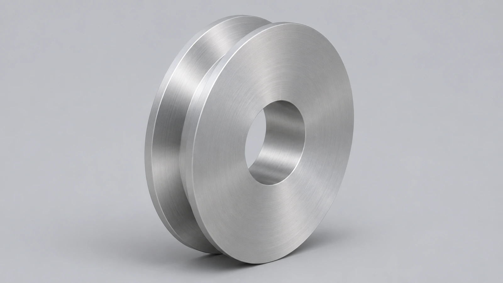
An aluminium V-belt pulley with a groove, a Ø16 bore and a keyway. Model it as one revolve of a half profile, then cut the keyway — the standard way to make turned parts.
 Kevin Walsh
- Level
- Intermediate
- Time
- 20 min
- Material
- Aluminium 6061, 2.70 g/cm³
- Check mass
- 193.19 g
The drawing
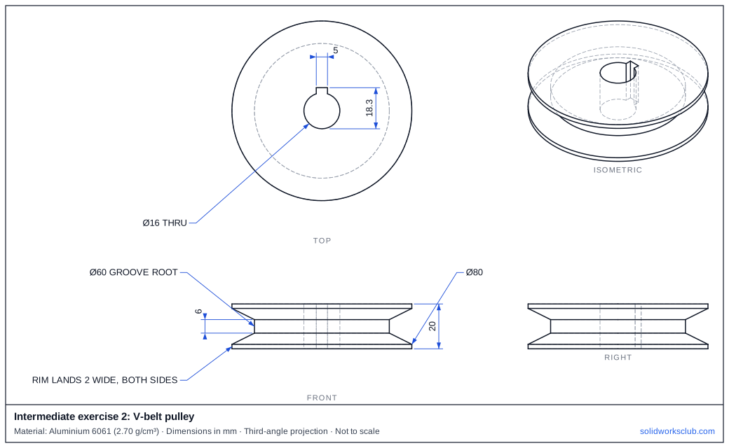
What you practise
- Revolving a closed half profile with sloped lines
- Reading groove dimensions from a section
- Keyway cut after a revolve
How to approach it
- Front plane: centreline, then the half profile from the bore (radius 8) to the rim (radius 40), 20 wide.
- Rim lands 2 mm wide at each side; groove root radius 30 and 6 wide; straight sloped flanks between.
- Revolve 360°.
- Keyway 5 wide, 18.3 from the far side of the bore.
Check your result
Apply Aluminium 6061 or a custom material with 2.70 g/cm³, then open Evaluate → Mass Properties. The mass should be 193.19 g (volume 71,552.65 mm³). Off by 1,000? Check the density units with the mass calculator.
Next: intermediate exercise 3.
Download files
Commands used
Show solution
- Half profile points (radius, axial): (8,0) (40,0) (40,2) (30,7) (30,13) (40,18) (40,20) (8,20) → Revolve 360°.
- Top face sketch: 5 mm rectangle reaching 10.3 mm from the axis → Cut Through All.
- Check the groove: the flanks drop 10 mm over 5 mm axial.
Frequently asked questions
Why revolve instead of extruding and cutting the groove?
+
One revolve captures every diameter at once and keeps the design intent of a turned part.
Related
- Intermediate exercise 3: ClevisIntermediate SOLIDWORKS exercise 3, clevis: slot cut from the top face. Drawing, STEP file and check mass 336.48 g. Free practice.
- Intermediate exercise 1: Pillow blockIntermediate SOLIDWORKS exercise 1, pillow block: combining a rectangular base, a web and a tangent boss. Drawing, STEP file and check mass 655.48 g.
- SOLIDWORKS RevolveHow to use Revolved Boss/Base and Revolved Cut in SOLIDWORKS: sketch half a profile, choose the axis, set the angle and fix open-sketch errors.
- Mass calculator for SOLIDWORKS and CSWA problemsCalculate part mass from volume and density in mm, cm, m or inches, with typical densities for steel, aluminium, brass and copper. Built for CSWA checks.