Intermediate exercise 16
Intermediate exercise 16: Motor mount plate
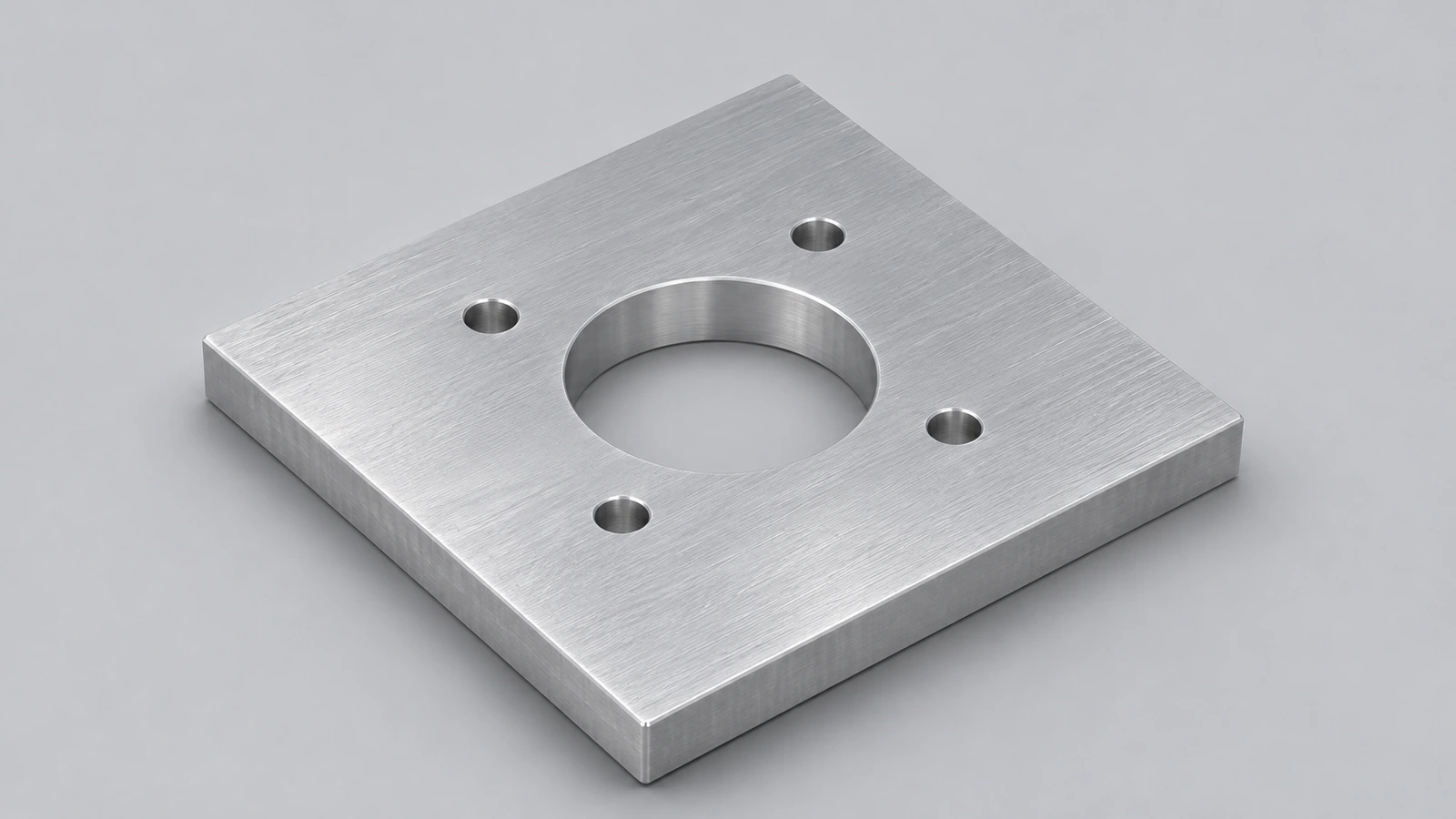
An aluminium motor mount plate: a central Ø40 opening, four Ø5.5 motor screw holes at 45°, two adjustment slots and chamfered corners.
 Kevin Walsh
- Level
- Intermediate
- Time
- 15 min
- Material
- Aluminium 6061, 2.70 g/cm³
- Check mass
- 174.81 g
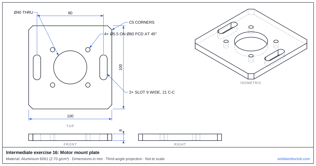
The drawing
What you practise
- Holes on a rotated pitch circle
- Vertical slots for adjustment
- Corner chamfers
How to approach it
- Plate 100 × 100 × 8, C5 on the vertical corner edges.
- Ø40 through at the centre.
- Four Ø5.5 on Ø60 at 45°, 135°, 225°, 315°.
- Two vertical slots 9 wide, 21 centre-to-centre, at x = ±40.
Check your result
Apply Aluminium 6061 or a custom material with 2.70 g/cm³, then open Evaluate → Mass Properties. The mass should be 174.81 g (volume 64,744.76 mm³). Off by 1,000? Check the density units with the mass calculator.
Next: intermediate exercise 17.
Download files
Commands used
Show solution
- Centre rectangle → Extrude 8 → Chamfer 5.
- Ø40 → Cut Through All.
- Ø5.5 at 45° on Ø60 → Cut → Circular Pattern 4.
- Two straight slots → Cut Through All.
Frequently asked questions
Why slots?
+
They let the motor slide to tension a belt before the screws are tightened.
Related
- Intermediate exercise 17: Spacer stack assemblyIntermediate SOLIDWORKS exercise 17, spacer stack assembly: inserting the first component fixed at the origin. Drawing, STEP file and check mass 645.55 g.
- Intermediate exercise 15: Eccentric camIntermediate SOLIDWORKS exercise 15, eccentric cam: offset bore dimensioned from the disk centre. Drawing, STEP file and check mass 341.81 g.
- SOLIDWORKS slot toolsHow to sketch slots in SOLIDWORKS: straight, centerpoint and arc slots, the Add dimensions option, and overall versus centre-to-centre length.
- Mass calculator for SOLIDWORKS and CSWA problemsCalculate part mass from volume and density in mm, cm, m or inches, with typical densities for steel, aluminium, brass and copper. Built for CSWA checks.