Simulation · Lesson 1
Your first static study
A linear static study answers "how much does it bend and how high is the stress" for a steady load. The workflow is always the same: material, connections, fixtures, loads, mesh, run, results. Do it once on a part whose answer you know, and you will spot wrong set-ups later.
 Kevin Walsh
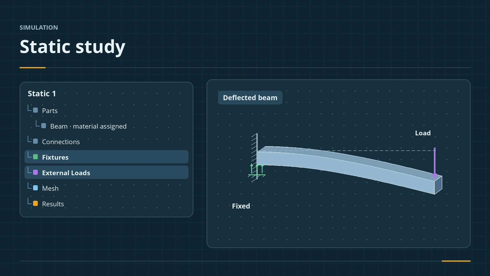
Where to find it
Tools → Add-Ins → SOLIDWORKS Simulation; Simulation tab → New Study → Static
The static workflow
| Step | Where | Note |
|---|---|---|
| Material | Right-click the part in the study tree | E, Poisson's ratio and yield matter most |
| Connections | Connections folder | Global Contact Bonded by default |
| Fixtures | Fixtures Advisor or right-click Fixtures | Remove rigid-body motion |
| Loads | External Loads | Force, pressure, gravity, torque, remote, bearing |
| Mesh | Right-click Mesh | Default is fine for a first run |
| Run | Run This Study | |
| Results | Results folder | Displacement first, then stress |
Linear static analysis assumes linear, elastic, isotropic material. Materials are set as in materials. Next: the mesh.
Mesh won't build? See mesh failed.
Step by step
-
1
Turn on Simulation
Tools → Add-Ins, tick SOLIDWORKS Simulation (and Start Up). A Simulation tab appears.
-
2
Model and new study
Extrude a 200 × 20 × 10 beam (10 mm in the load direction). Apply Alloy Steel. Simulation → New Study → Static.
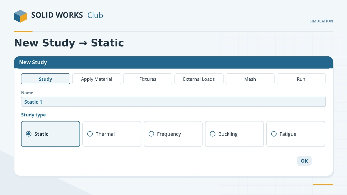
Static is the default study type for steady loads. -
3
Fixture and load
Fixed Geometry on one 20 × 10 end face. Force of 100 N on the opposite end face, direction downward (normal to the 20 mm top face — pick it as the direction reference).
-
4
Mesh and run
Right-click Mesh → Create Mesh (default settings), then Run This Study.
-
5
Read the results
Open the displacement plot first — huge values mean a missing fixture. Then the von Mises stress plot.
Common mistakes
- No fixture or too few — the model can move as a rigid body and the study fails or gives huge displacements.
- Reading peak stress at the fixed edge — it is a singularity (lesson 4).
- Stresses above yield in a linear study — the numbers are no longer accurate; you need a nonlinear study.
Lesson 1 of 6 in the simulation course.
Practice
Run the beam with Fixed Geometry at one end and 100 N downward on the free end face. Check: the maximum resultant displacement is close to δ = FL³/(3EI) = 0.76 mm for E = 210 GPa — use the E in your material dialog; within a few percent is a good result.
Sources
- Javelin — Basic setup steps for an FEA static simulation (Jan 2024)
- SOLIDWORKS Tech Blog — Simulation vs SimulationXpress (Sep 2017)
- GoEngineer — Degrees of freedom and fixtures (Jul 2024)
- SOLIDWORKS Tech Blog — Getting started: fixtures and loads (Nov 2018)
- SOLIDWORKS Tech Blog — Get connected with contacts (Nov 2016)
- GoEngineer — Simulation global contact explained (Feb 2018)
- CATI — Tips for post-processing in Simulation (Apr 2021)
- Engineers Rule — Simulation essentials for SOLIDWORKS professionals (Jun 2020)
- SOLIDWORKS Blog — Material properties in analysis (May 2012)
Checked November 2026. SOLID WORKS Club is independent; menu names can differ slightly between releases.
Frequently asked questions
How do I start a static analysis in SOLIDWORKS?
+
Turn on the Simulation add-in, then Simulation tab → New Study → Static. Add material, fixtures and loads, mesh and run.
Why is the Simulation tab missing?
+
The add-in is off. Turn it on in Tools → Add-Ins and tick Start Up to keep it loaded.
What contact is used in assemblies by default?
+
Global Contact set to Bonded, applied to faces that touch at the start. Local contact sets override it.
Can I do this without Simulation?
+
For single parts, SimulationXpress (Tools → Xpress Products) runs the same kind of linear static study.
Related
- Meshing in SOLIDWORKS SimulationSOLIDWORKS Simulation meshing: blended curvature-based mesher, density slider, mesh controls, draft vs high quality elements, aspect ratio, convergence.
- Fixtures, loads and contactsFixtures, loads and contacts in SOLIDWORKS Simulation: fixed geometry, roller/slider, hinge, force, pressure, gravity, remote loads, bonded vs no penetration.
- Results and factor of safetyRead SOLIDWORKS Simulation results: displacement, von Mises stress, factor of safety plots, probes, reports, and why peaks at sharp corners mislead.
- SOLIDWORKS materialsHow to apply materials in SOLIDWORKS, create a custom material library, set materials per body, keep your colours, and link the material to a custom property.