Simulation · Lesson 2
Meshing in SOLIDWORKS Simulation
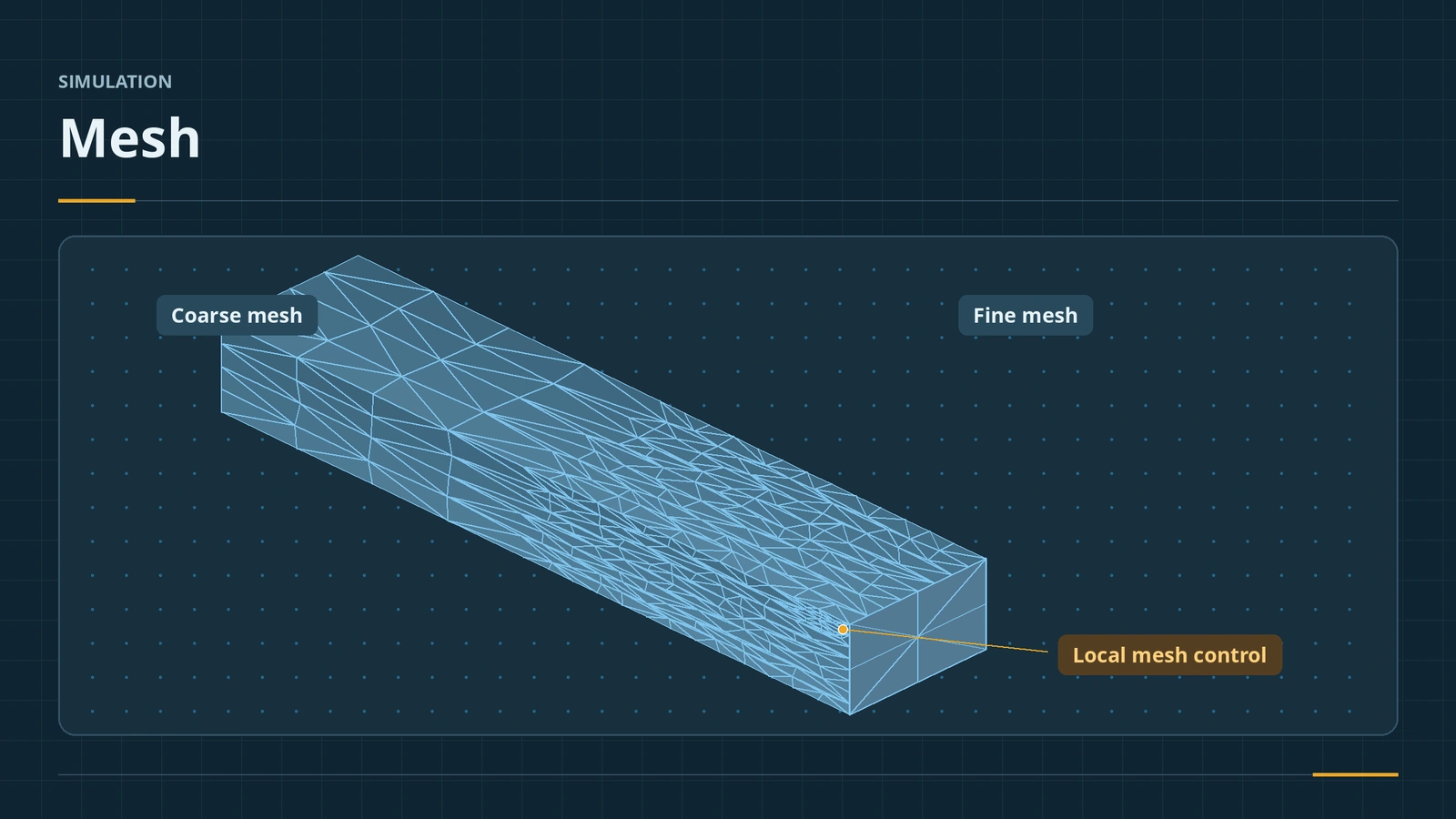
FEA splits the model into small elements — the mesh — and solves for each one. A finer mesh is more accurate and slower. Stress depends strongly on the mesh; displacement much less. The way to know your answer is good is to refine and see whether it stops changing: convergence.
 Kevin Walsh
Where to find it
Study tree → right-click Mesh → Create Mesh / Apply Mesh Control / Details
Elements
| Element | Used for |
|---|---|
| Solid tetrahedral, high quality (10 nodes) | Default for solid bodies |
| Solid tetrahedral, draft (4 nodes) | Quick checks; can mix with high quality since 2020 |
| Shell | Sheet metal and surface bodies |
| Beam (2 nodes) | Weldment members |
Rules of thumb: about two elements through the thickness and around fillets. Frequency studies need a less fine mesh than stress studies. Adaptive methods are on the static study's Adaptive tab. Peaks that never converge are explained in results and factor of safety.
When the mesh fails: see mesh failed for Failure Diagnostics and mesh controls.
Step by step
-
1
Open the mesh settings
In the beam's static study, right-click Mesh → Create Mesh. Note the mesher (Blended curvature-based is the default for new studies) and the density slider from Coarse to Fine.
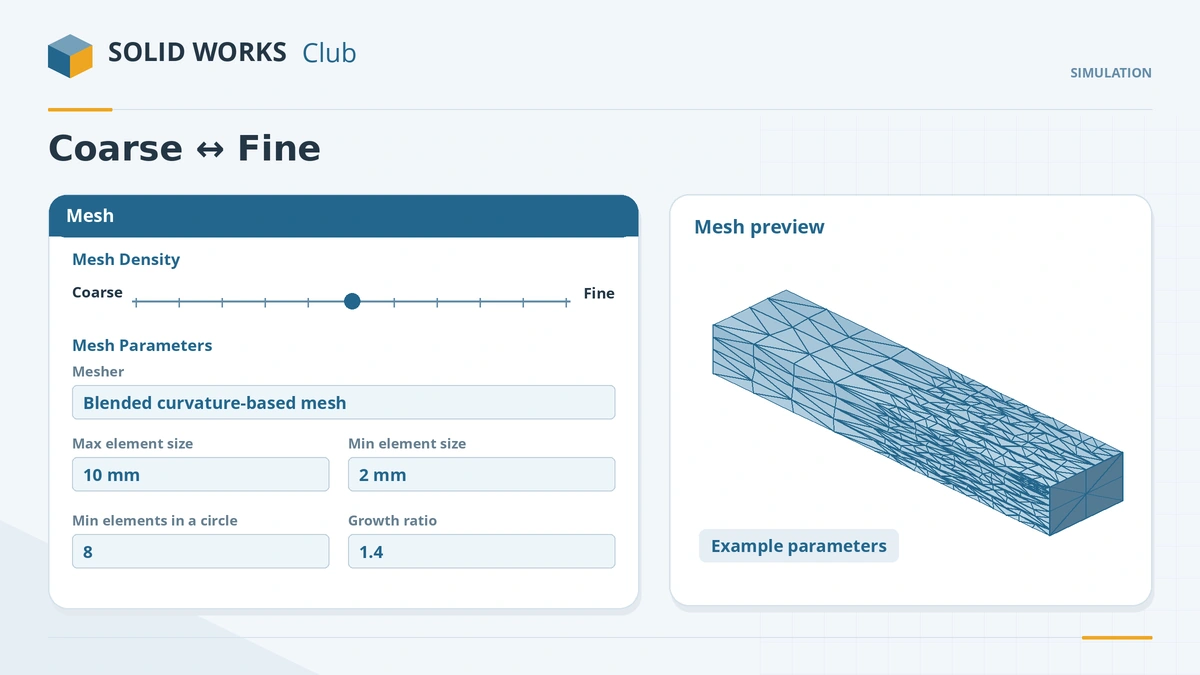
The density slider runs from coarse to fine; blended curvature-based is the usual mesher. -
2
Check quality
Right-click Mesh → Details: element count and the share of elements with aspect ratio under 3 (ideally 90% or more).
-
3
Refine and compare
Run at the default density, note the mid-length stress, then move the slider to Fine, re-mesh and run again.
-
4
Local control
For small features, right-click Mesh → Apply Mesh Control on the faces or edges and set a smaller element size there.
Common mistakes
- Trusting one run — compare at least two mesh densities.
- Thin sheet bodies meshed as solids — they give distorted elements; use shells (default for sheet metal).
- Draft-quality elements for final stresses — use high quality (second order) for the final run.
Lesson 2 of 6 in the simulation course.
Practice
Run the beam at default and Fine mesh density. Check: the probed stress at mid-length on the top face stays close to 30 MPa in both runs, while the peak stress at the fixed end keeps rising — the difference between a converged result and a singularity.
Sources
- Javelin — Mesh parameters in Simulation (Dec 2022)
- Javelin — 2021 enhanced blended curvature-based mesher (Oct 2020)
- CATI — 2021 what's new: meshing enhancements (Oct 2020)
- Javelin — 2020 mixed draft and high quality mesh (Oct 2019)
- Hawk Ridge — Meshing elements for Simulation (Aug 2018)
- Javelin — Simulation mesh refinement (Jul 2025)
- GoEngineer — Solution adaptive mesh refinement (Apr 2018)
- CATI — Making sense of Simulation meshing, part 1 (May 2017)
- TriMech — What is aspect ratio?
Checked November 2026. SOLID WORKS Club is independent; menu names can differ slightly between releases.
Frequently asked questions
Which mesher does SOLIDWORKS Simulation use by default?
+
Blended curvature-based for new studies in recent versions. Standard and curvature-based are alternatives.
What is the difference between draft and high quality mesh?
+
High quality uses second-order 10-node tetrahedra (default); draft uses first-order 4-node elements, fine for quick checks.
What is a good aspect ratio?
+
3 or less is ideal, for at least 90% of elements; above 20 can destabilise the solver.
What are h-adaptive and p-adaptive?
+
Automatic refinement: h-adaptive makes elements smaller where error is high; p-adaptive raises element order.
Related
- Your first static studyRun your first SOLIDWORKS static study: add-in, material, fixtures, loads, contacts, mesh and run, then check the deflection against beam theory.
- Results and factor of safetyRead SOLIDWORKS Simulation results: displacement, von Mises stress, factor of safety plots, probes, reports, and why peaks at sharp corners mislead.
- Fixtures, loads and contactsFixtures, loads and contacts in SOLIDWORKS Simulation: fixed geometry, roller/slider, hinge, force, pressure, gravity, remote loads, bonded vs no penetration.
- Frequency studiesRun a SOLIDWORKS frequency study: natural frequencies and mode shapes, number of frequencies, free vs fixed parts, mass participation and a beam check.