Sheet metal · Lesson 2
Edge Flange in SOLIDWORKS sheet metal
Edge Flange bends a wall up from an edge of a sheet metal part, using the part's thickness and bend radius. Two settings decide the final size: how the length is measured (to the outer or inner virtual sharp, or to the bend tangent) and where the flange sits relative to the edge (material inside, material outside, bend outside and more). Get them right and the drawing dimension matches the part.
 Kevin Walsh
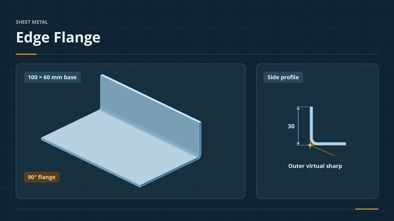
Where to find it
Sheet Metal tab → Edge Flange; select a linear edge
Length and position options
| Option | Choices |
|---|---|
| Flange length | Blind or Up To Edge And Merge |
| Measured from | Outer Virtual Sharp, Inner Virtual Sharp, Tangent Bend |
| Flange position | Material Inside, Material Outside, Bend Outside, Bend from Virtual Sharp, Tangent to Bend |
| Angle | Value or parallel/perpendicular to a face |
| Custom relief | Obround, rectangle or tear for this flange only |
| Multi-Length Flange (2025+) | A different length per edge |
Since 2015 Edit Flange Profile opens a rectangular sketch you can reshape freely. Since 2025 a document property can add flange length dimensions automatically. The flat length of this flange is worked out step by step in the K-factor calculator.
Practise it: four edge flanges make the sheet metal box project.
Step by step
-
1
Pick the edge
Open the 100 × 60 base flange. Edge Flange, click one of the 100 mm top edges and drag the preview upward.
-
2
Set angle and length
Angle 90°. Flange Length: Blind, 30 mm, measured from the Outer Virtual Sharp.
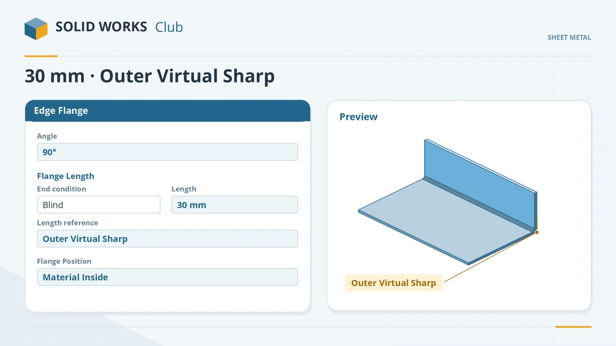
Length to the outer virtual sharp plus Material Inside keeps outside dimensions exact. -
3
Set the position
Flange Position: Material Inside, so the flange stays inside the base outline and the 60 mm dimension does not change. Click the tick.
-
4
Reshape if needed
Right-click the flange's sketch → Edit Sketch (or use Edit Flange Profile during creation) to make a partial or shaped flange instead of cutting it afterwards.
Common mistakes
- Wrong flange position — Material Outside adds the thickness to the base, so 60 becomes 62.
- Tangent Bend length with an angle below 90° — it errors and resets to 90°; use a virtual sharp option.
- Cutting a flange to shape with Extrude Cut — Edit Flange Profile gives the same flat and rebuilds faster.
Lesson 2 of 13 in the sheet metal course.
Practice
Add a 30 mm edge flange to a 100 mm edge, outer virtual sharp, material inside. Check: the part measures 100 × 60 × 30 outside, Mass Properties shows 17,342.48 mm³, and the flat pattern is 100 × 86.71 mm.
Sources
- Engineers Rule — Sheet metal success in SOLIDWORKS (Apr 2016)
- SolidWorks Tutorials for Beginners — Sheet metal tutorials (Dec 2019)
- CADSoftUSA — Sheet metal tools and commands (Mar 2026)
- DriveWorks — Sheet metal features reference
- Hawk Ridge — Tangent Bend option and edge flange angle
- Hawk Ridge — Shaping a sheet metal edge flange (Mar 2016)
- Javelin — Auto vs corner relief (Dec 2010)
- SOLIDWORKS blog — Sheet metal tutorial PDF (Mark Eilers)
- GoEngineer — SOLIDWORKS 2025 sheet metal what's new (Nov 2024)
- Solid Solutions — Sheet metal features in SOLIDWORKS 2025 (Dec 2024)
Checked November 2026. SOLID WORKS Club is independent; menu names can differ slightly between releases.
Frequently asked questions
How do I add a flange in SOLIDWORKS sheet metal?
+
Click Edge Flange, select a linear edge, set the angle, the length and the flange position, and click OK.
What is the outer virtual sharp?
+
The point where the outside faces of the two walls would meet without the bend. Measuring flange length to it matches the outside dimension.
What do the flange position options mean?
+
They place the flange relative to the selected edge: material inside, material outside, bend outside, bend from virtual sharp or tangent to bend.
Can one edge flange have different lengths?
+
Since SOLIDWORKS 2025, the Multi-Length Flange option sets a different length for each selected edge.
Related
- Base Flange — the first sheet metal featureStart a SOLIDWORKS sheet metal part with Base Flange/Tab: open and closed profiles, thickness, bend radius, K-factor, gauge tables and auto relief.
- Miter Flange in SOLIDWORKS sheet metalUse the SOLIDWORKS Miter Flange: sketch a profile normal to an edge, run it along connected edges, set gap, offsets and position, and avoid errors.
- Hems in SOLIDWORKS sheet metalAdd a hem in SOLIDWORKS sheet metal: closed, open, tear drop and rolled types, bend position, length, gap and radius, hem width and design rules.
- K-factor calculator for sheet metal bendsFree sheet metal K-factor calculator: bend allowance, bend deduction, outside setback and flat length for one bend, or the K-factor from a test bend.