Sheet metal · Lesson 3
Miter Flange in SOLIDWORKS sheet metal
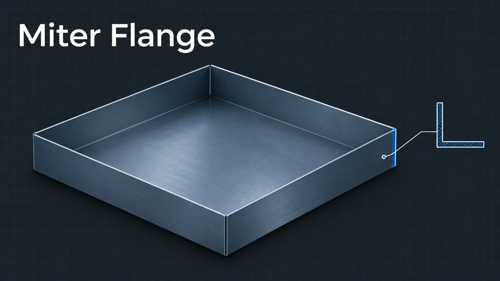
Miter Flange sweeps a profile — a line, an L or an arc — along one or more connected edges and mitres the corners where they meet. It builds a whole rim around a plate in one feature with a correct flat pattern, something a set of edge flanges cannot do. The profile sketch sits on a plane normal to the first edge.
 Kevin Walsh
Where to find it
Sheet Metal tab → Miter Flange (sketch on a plane normal to the first edge)
Options
| Option | Use |
|---|---|
| Edges | First edge from the sketch; add connected edges |
| Propagate | Carry the flange onto further connected edges |
| Flange position | Material Inside, Material Outside, Bend Outside |
| Trim side bends | Trims bends of neighbouring flanges |
| Gap distance | Gap at the mitred corners |
| Start / End offset | Pull the flange back from the chain's ends |
Corners between separate flanges are closed with the tools in corners.
Step by step
-
1
Sketch the profile
On a new 100 × 60 base flange (2 mm), select the end face of one long edge or a plane normal to that edge. Sketch a 20 mm line starting at the top edge and going up.
-
2
Start Miter Flange
With the sketch active, click Miter Flange. The first edge is picked for you.
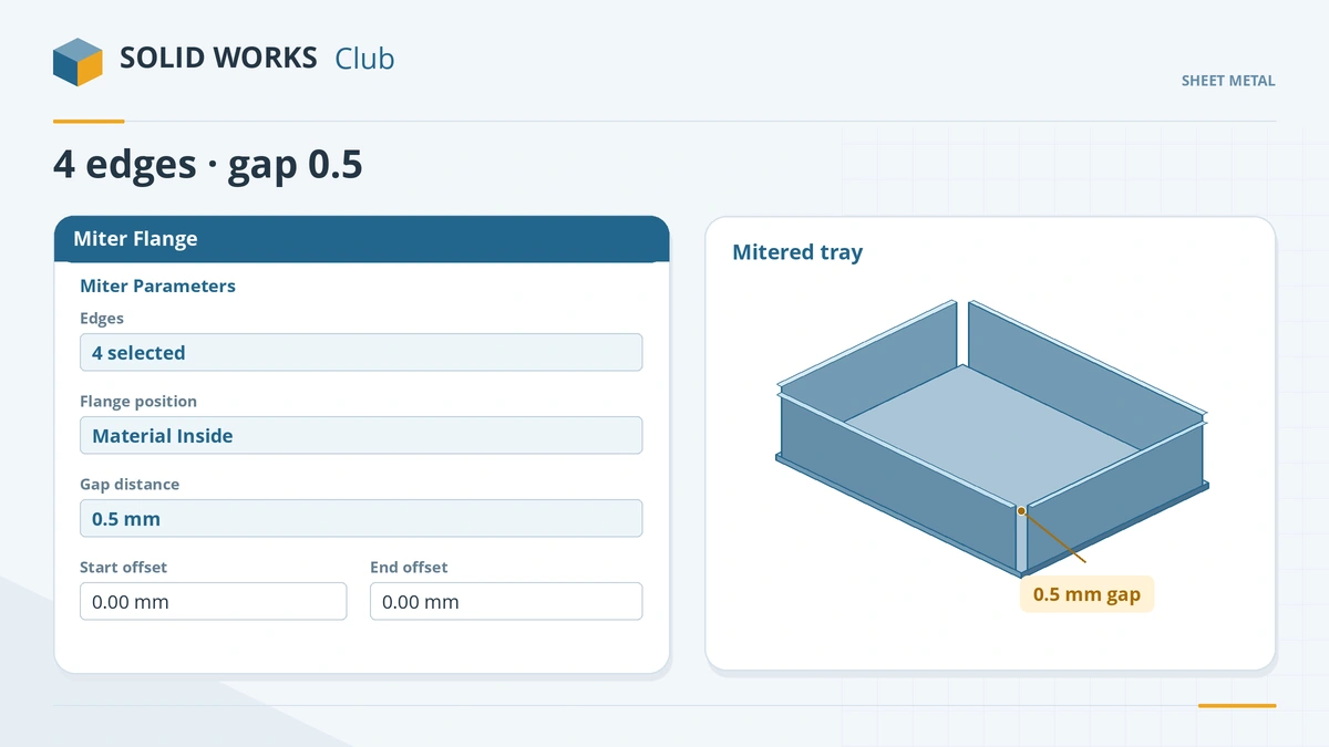
One profile runs along all selected edges; corners get a gap. -
3
Add the other edges
Select the remaining three top edges. Set Material Inside and a gap distance of 0.5 mm. Click the tick.
-
4
Check the flat
Flatten. The four walls unfold around the base with mitred corners and the gap between them.
Common mistakes
- Profile not on a plane normal to the first edge — the feature cannot start.
- 'Unable to make a miter flange' with a line straight off the edge — angling the line can fix it; if the preview shows, it will build.
- Simplify Bends left on in the flat pattern, losing rounded miter edges the welder needs.
Lesson 3 of 13 in the sheet metal course.
Practice
Run a 20 mm miter flange around all four top edges of a 100 × 60 base with a 0.5 mm gap. Check: one Miter Flange feature, and the cut list shows Bends: 4.
Sources
- GoEngineer — Exterior miter flange tip (Mar 2017)
- Javelin — The perfect sheet metal miter flange (Oct 2020)
- SolidWorks Tutorials for Beginners — Sheet metal tutorials (Dec 2019)
- DriveWorks — Sheet metal features reference
- SOLIDWORKS blog — Sheet metal tutorial PDF (Mark Eilers)
- CADSoftUSA — Sheet metal tools and commands (Mar 2026)
Checked November 2026. SOLID WORKS Club is independent; menu names can differ slightly between releases.
Frequently asked questions
How do I make a miter flange in SOLIDWORKS?
+
Sketch a profile on a plane normal to an edge, click Miter Flange, pick further connected edges, set gap and position, and click OK.
Why do I get "Unable to make a miter flange"?
+
Often the profile is a line straight off the edge or not normal to it. Change the sketch angle or plane; if a preview appears, it will build.
What is the gap distance?
+
The gap left between neighbouring flanges at the mitred corners.
Miter Flange or Edge Flange?
+
Edge Flange for single walls with simple profiles; Miter Flange for a profile running along several connected edges with mitred corners.
Related
- Edge Flange in SOLIDWORKS sheet metalAdd a SOLIDWORKS edge flange: length to outer or inner virtual sharp, flange position, angle, Edit Flange Profile, custom relief and multi-length.
- Sheet metal cornersFinish SOLIDWORKS sheet metal corners: Closed Corner butt, overlap and underlap, Break Corner fillets and chamfers, Corner Relief and Welded Corner.
- Hems in SOLIDWORKS sheet metalAdd a hem in SOLIDWORKS sheet metal: closed, open, tear drop and rolled types, bend position, length, gap and radius, hem width and design rules.
- Flat patterns in SOLIDWORKS sheet metalHow the SOLIDWORKS flat pattern works: Flatten, Flat-Pattern options, Unfold and Fold for cuts across bends, bend lines and flat drawing views.