Tools
K-factor calculator for sheet metal bends
Enter the sheet thickness, inside bend radius, bend angle and K-factor, and the calculator gives the bend allowance, bend deduction, outside setback and the flat length of a two-flange part. Or work backwards: bend a test strip of known length, measure its legs, and get the K-factor your press brake actually produces — the value to type into SOLIDWORKS.
 Kevin Walsh
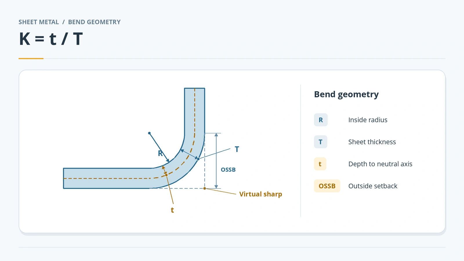
The formulas
| Value | Formula |
|---|---|
| K-factor | K = t / T (neutral axis distance ÷ thickness) |
| Bend allowance | BA = A × (R + K·T), A in radians |
| Outside setback | OSSB = tan(A/2) × (R + T) |
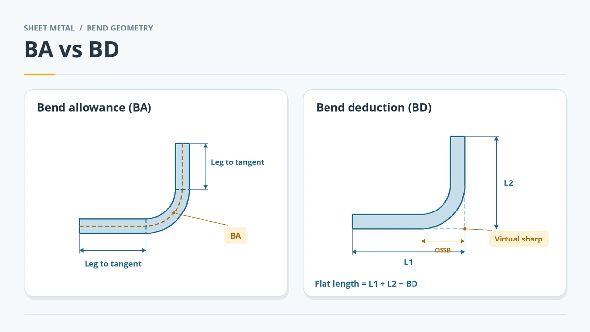
| Bend deduction | BD = 2 × OSSB − BA |
| Flat length | L1 + L2 − BD (legs to the virtual sharp) |
| K from a test bend | BD = L1 + L2 − flat; BA = 2·OSSB − BD; K = (BA / A − R) / T |
Worked example: 2 mm sheet, 2 mm inside radius, 90° bend, K = 0.5. BA = 1.5708 × (2 + 1) = 4.712 mm. OSSB = tan 45° × 4 = 4 mm, so BD = 8 − 4.712 = 3.288 mm. An L-bracket with outside legs of 60 and 30 mm has a flat length of 90 − 3.288 = 86.71 mm. With K = 0.33 the flat becomes 86.18 mm — half a millimetre shorter.
Choosing a K-factor
Ask your fabricator first: many shops keep their own tables for SOLIDWORKS. If you have nothing else, SOLIDWORKS' tech blog suggests starting at 0.5, and K-factors usually fall between about 0.3 and 0.5. One reseller's rule of thumb by radius:
| Inside radius | K-factor |
|---|---|
| R less than T | 0.25 |
| R from T to 2T | 0.33 |
| R more than 2T | 0.5 |
The most reliable value comes from a test bend: cut a strip, measure it, bend it 90° on the press brake you will use, measure both outside legs, and enter them in the second mode above. Bend deduction should never exceed twice the outside setback; if the calculator returns a K outside 0–1, a leg was measured to the wrong reference.
Using the result in SOLIDWORKS
Type the K-factor in the Bend Allowance section of the Base Flange or the Sheet-Metal feature, or put it in a gauge table so every part uses the same values. K-factor is SOLIDWORKS' default bend calculation; bend tables, bend allowance, bend deduction and bend calculation are the alternatives — see K-factor and bend tables. The flat length shows in the flat pattern and the cut list's bounding box.
Practise it: check the blank of the sheet metal box project.
Sources
- Javelin — What are bend allowance, bend deduction and K-factor? (Jun 2017)
- Javelin — Calculating bend allowance, bend deduction and K-factor (Jun 2017)
- The Fabricator — K-factors, Y-factors and press brake bending precision (Mar 2018)
- Solid Solutions — What is a K-factor? (Aug 2023)
- SOLIDWORKS Tech Blog — Understanding bend allowance options (Oct 2014)
- GoEngineer — SOLIDWORKS sheet metal bend calculations explained (May 2022)
Checked November 2026. SOLID WORKS Club is independent; menu names can differ slightly between releases.
Frequently asked questions
What is the K-factor in sheet metal?
+
The position of the neutral axis as a fraction of the thickness: K = t / T. 0 is the inside face, 0.5 the middle and 1 the outside face.
How do I calculate bend allowance?
+
BA = A × (R + K × T), with the bend angle A in radians. A 90° bend in 2 mm sheet with a 2 mm radius and K = 0.5 has BA = 4.712 mm.
What is the difference between bend allowance and bend deduction?
+
Bend allowance is the arc length of the bend on the neutral axis; you add it to legs measured to the bend tangent lines. Bend deduction is subtracted from legs measured to the virtual sharp: BD = 2 × OSSB − BA.
What K-factor should I use?
+
Ask your fabricator first. As a rough guide, about 0.33 to 0.5 for most air bending; one reseller suggests 0.25, 0.33 or 0.5 depending on the radius-to-thickness ratio.
Related
- K-factor, bend tables and gauge tablesHow SOLIDWORKS calculates flat lengths: K-factor, bend allowance, bend deduction, bend calculation, bend tables and gauge tables, and where to set each.
- Flat patterns in SOLIDWORKS sheet metalHow the SOLIDWORKS flat pattern works: Flatten, Flat-Pattern options, Unfold and Fold for cuts across bends, bend lines and flat drawing views.
- Base Flange — the first sheet metal featureStart a SOLIDWORKS sheet metal part with Base Flange/Tab: open and closed profiles, thickness, bend radius, K-factor, gauge tables and auto relief.
- SOLIDWORKS sheet metal — 13 lessonsFree SOLIDWORKS sheet metal course: base, edge and miter flanges, hems, jogs, bends, corners, forming tools, flat patterns, K-factor and DXF export.