Sheet metal · Lesson 1
Base Flange — the first sheet metal feature
A sheet metal part usually starts with Base Flange/Tab. Sketch a closed profile for a flat blank or an open profile for a bent section, and the feature adds thickness. It also sets the part's defaults — thickness, bend radius, bend allowance and relief — which every later flange, hem and bend inherits. SOLIDWORKS adds a Sheet-Metal feature and a Flat-Pattern to the tree.
 Kevin Walsh
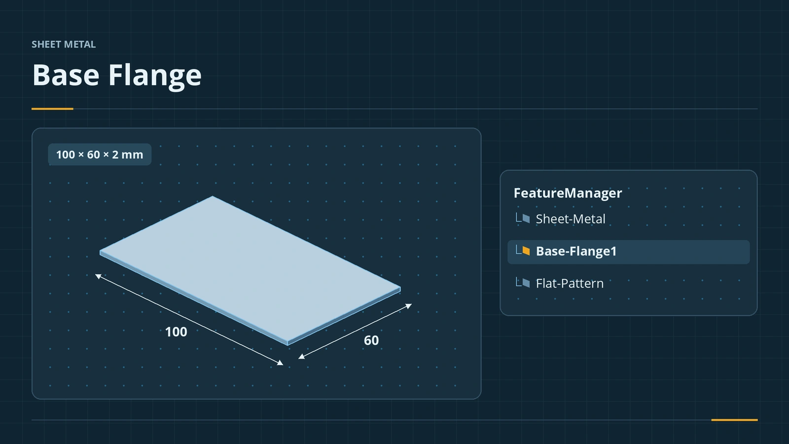
Where to find it
Sheet Metal tab → Base Flange/Tab; Insert → Sheet Metal → Base Flange
Base Flange options
| Section | What it sets |
|---|---|
| Direction 1 | Depth for open profiles, like an extrude |
| From (2026+) | Start offset from the sketch plane, a vertex or a face |
| Sheet Metal Gauges | Use a gauge table instead of typed values |
| Sheet Metal Parameters | Thickness, bend radius, reverse direction |
| Bend Allowance | K-Factor (default 0.5), bend allowance, bend deduction, bend table, bend calculation |
| Auto Relief | Rectangular, tear or obround, with relief ratio |
Profile types
- Closed profile — a flat blank (a tab), like our 100 × 60 plate.
- Open profile — a bent section such as an L or U, given a depth in Direction 1.
- Several closed profiles — nested contours give a blank with cut-outs.
Since 2013 sheet metal bodies and their flat patterns sit in separate folders in the tree. The bend values are explained in K-factor and bend tables.
Step by step
-
1
Show the Sheet Metal tab
In a new part, right-click any CommandManager tab and tick Sheet Metal if the tab is missing.
-
2
Sketch the blank
On the Top plane, sketch a 100 × 60 rectangle centred on the origin.
-
3
Base Flange
Base Flange/Tab. Under Sheet Metal Parameters set thickness 2 and bend radius 2. Under Bend Allowance keep K-Factor 0.5; under Auto Relief keep Rectangular. Click the tick.
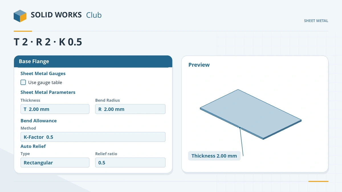
Thickness, radius, bend allowance and relief set here become the part's defaults. -
4
Look at the tree
The tree now has a Sheet-Metal feature (the defaults), the Base-Flange1 feature and a Flat-Pattern folder. Change defaults later by editing Sheet-Metal.
Common mistakes
- Building sheet metal with Extrude and then wondering why it will not flatten — start with Base Flange or convert the solid.
- Bend radius smaller than the thickness — the metal can crack; a radius at least equal to the thickness is a safe start.
- Keeping K = 0.5 for production parts — the default is often not right; get values from your fabricator.
Lesson 1 of 13 in the sheet metal course.
Practice
Make the 100 × 60 base flange, 2 mm thick, R2, K 0.5. Check: Mass Properties shows a volume of 12,000 mm³. Keep the part — the next lessons add flanges to it.
Sources
- Hawk Ridge — Sheet metal: a beginner's guide (Jun 2017)
- SolidProfessor — Top 7 FAQs about sheet metal (Jul 2019)
- Engineers Rule — Sheet metal success in SOLIDWORKS (Apr 2016)
- CADSoftUSA — Sheet metal tools and commands (Mar 2026)
- TriMech — Why is my flat pattern length incorrect? (Mar 2025)
- GoEngineer — SOLIDWORKS sheet metal bend calculations explained (May 2022)
- Javelin — Auto vs corner relief (Dec 2010)
- DriveWorks — Sheet metal features reference
- Engineers Rule — How to set up sheet metal gauge tables (Dec 2016)
- Javelin — How to create a custom sheet metal bend table (Jun 2017)
- SolidWorks Tutorials for Beginners — Sheet metal tutorials (Dec 2019)
- CATI — Sheet metal multibody parts in SOLIDWORKS 2013 (Apr 2013)
- GoEngineer — SOLIDWORKS 2026 parts and features (Oct 2025)
- Javelin — Part modeling: what's new in SOLIDWORKS 2026 (Oct 2025)
Checked November 2026. SOLID WORKS Club is independent; menu names can differ slightly between releases.
Frequently asked questions
How do I start a sheet metal part in SOLIDWORKS?
+
Sketch a profile and click Base Flange/Tab on the Sheet Metal tab. Set thickness, bend radius and bend allowance; they become the part's defaults.
Can a base flange use an open sketch?
+
Yes. A closed profile gives a flat blank; an open profile is extruded like a thin feature with bends at its corners.
What is the default K-factor in SOLIDWORKS?
+
K-Factor is the default bend calculation and the default value is 0.5, which is often not correct for real parts.
What auto relief types are there?
+
Rectangular, Tear and Obround. Rectangular and obround reliefs use a relief ratio between 0.05 and 2.0 times the thickness.
Related
- Edge Flange in SOLIDWORKS sheet metalAdd a SOLIDWORKS edge flange: length to outer or inner virtual sharp, flange position, angle, Edit Flange Profile, custom relief and multi-length.
- K-factor, bend tables and gauge tablesHow SOLIDWORKS calculates flat lengths: K-factor, bend allowance, bend deduction, bend calculation, bend tables and gauge tables, and where to set each.
- SOLIDWORKS Extruded Boss/BaseHow to use Extruded Boss/Base in SOLIDWORKS: every end condition from Blind to Mid Plane, Direction 2, draft, thin features, Selected Contours and Merge result.
- SOLIDWORKS sheet metal — 13 lessonsFree SOLIDWORKS sheet metal course: base, edge and miter flanges, hems, jogs, bends, corners, forming tools, flat patterns, K-factor and DXF export.