Sheet metal · Lesson 6
Sketched Bend in SOLIDWORKS sheet metal
Sketched Bend folds an existing flat sheet along lines you draw on it. It suits work that starts from a known blank — when the flat size is fixed by tooling or a customer drawing — because the flat pattern stays exactly the blank you began with. Lines can run at any angle to the edges.
 Kevin Walsh
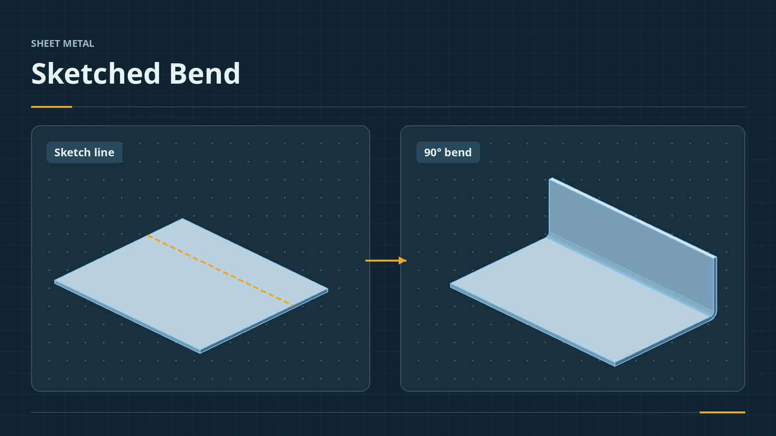
Where to find it
Sheet Metal tab → Sketched Bend
Bend positions
| Position | Where the bend sits |
|---|---|
| Bend Centerline | Centred on the line (default) |
| Material Inside | Material stays inside the line |
| Material Outside | Material moves outside the line |
| Bend Outside | Whole bend outside the line |
The radius comes from the Sheet-Metal defaults unless you clear Use default radius; Custom Bend Allowance overrides the bend value. Flattening is covered in flat pattern.
Step by step
-
1
Sketch the bend line
On a 100 × 60 base flange (2 mm), sketch a line on the top face parallel to the 100 mm edge, 20 mm from it. Exit the sketch.
-
2
Start Sketched Bend
Select the sketch and click Sketched Bend. Click the larger side of the plate as the fixed face.
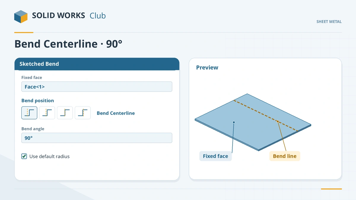
Pick the side that stays still, then the bend position and angle. -
3
Set position and angle
Bend position Bend Centerline (the default), angle 90°, default radius. Click the tick.
-
4
Flatten
Flatten. The blank is the plate you started with.
Common mistakes
- Clicking the wrong side as the fixed face — the "wrong" side moves.
- Expecting outside dimensions to match the sketch — the bend position decides where the material ends up.
- Using Sketched Bend for walls that need an exact outside height — Edge Flange is easier for that.
Lesson 6 of 13 in the sheet metal course.
Practice
Bend the 100 × 60 plate 90° along a line 20 mm from a long edge. Check: the flat pattern bounding box is still 100 × 60 mm — a sketched bend never changes the blank.
Sources
- GoEngineer — Sheet metal sketched bend tutorial (May 2024)
- TriMech — Using the Sketched Bend command (Oct 2022)
- GoEngineer — Sheet metal tutorial: flat pattern and sketched bend (Feb 2020)
- DriveWorks — Sheet metal features reference
- SOLIDWORKS blog — Sheet metal tutorial PDF (Mark Eilers)
Checked November 2026. SOLID WORKS Club is independent; menu names can differ slightly between releases.
Frequently asked questions
How do I bend sheet metal along a line in SOLIDWORKS?
+
Sketch the bend line on a face, click Sketched Bend, pick the fixed face, set the bend position and angle, and click OK.
What bend positions are there?
+
Bend Centerline (default), Material Inside, Material Outside and Bend Outside.
Can I bend only part of the sheet?
+
Yes. Colinear lines can bend some areas while a tab between them stays flat.
When should I use Sketched Bend?
+
When you start from a known flat blank, for example a size fixed by tooling, and want the flat to stay exactly that size.
Related
- Jog in SOLIDWORKS sheet metalUse the SOLIDWORKS sheet metal Jog: one sketched line, fixed face, jog offset and dimension position, jog position, angle, Fix projected length.
- Flat patterns in SOLIDWORKS sheet metalHow the SOLIDWORKS flat pattern works: Flatten, Flat-Pattern options, Unfold and Fold for cuts across bends, bend lines and flat drawing views.
- Edge Flange in SOLIDWORKS sheet metalAdd a SOLIDWORKS edge flange: length to outer or inner virtual sharp, flange position, angle, Edit Flange Profile, custom relief and multi-length.
- Sheet metal cornersFinish SOLIDWORKS sheet metal corners: Closed Corner butt, overlap and underlap, Break Corner fillets and chamfers, Corner Relief and Welded Corner.