Sheet metal · Lesson 8
Forming tools in SOLIDWORKS sheet metal
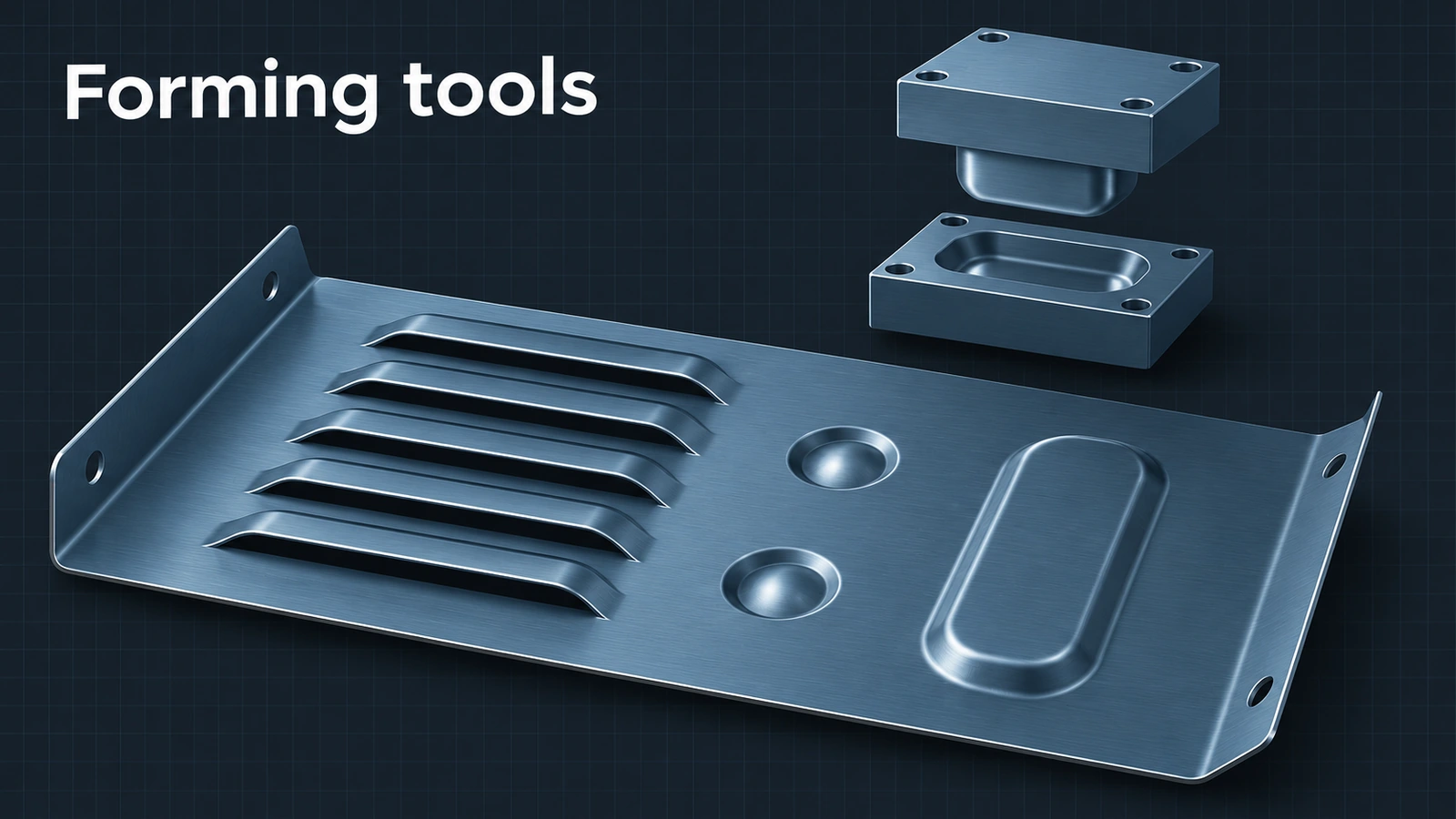
Forming tools press shapes into sheet metal — louvers, lances, dimples, ribs, embosses. You drag a tool from the Design Library onto a face and position it with a sketch. Your own tools are ordinary parts with a Forming Tool feature that marks the stopping face and any faces to remove, saved as .sldftp. Since 2024, simple indents can also be made with the Stamp feature.
 Kevin Walsh
Where to find it
Design Library → forming tools; Sheet Metal tab → Forming Tool; File → Save As → Form Tool (*.sldftp)
Forming tool parts
| Element | Use |
|---|---|
| Stopping face | Face that butts against the sheet and sets depth (teal in preview) |
| Faces to remove | Become holes in the sheet (red in preview) |
| Insertion point | Placement point; by default the stopping face centroid |
| Configurations | Different sizes of one tool, chosen when placing |
| Split Line | Removes only part of a face |
Shipped tools may still use the older method with an orientation sketch and red faces; they can be updated with a Forming Tool feature. The Design Library itself is covered in Design Library.
Step by step
-
1
Model the tool
In a new part, extrude a 60 × 60 × 10 block. On its top face, extrude a 20 × 10 slot-shaped boss, 3 mm high, and fillet its edges with a radius of at least 2 (the sheet thickness).
-
2
Add the Forming Tool feature
Forming Tool (Sheet Metal tab). Stopping face: the top of the block. Leave Faces to remove empty for an emboss. Check the insertion point.
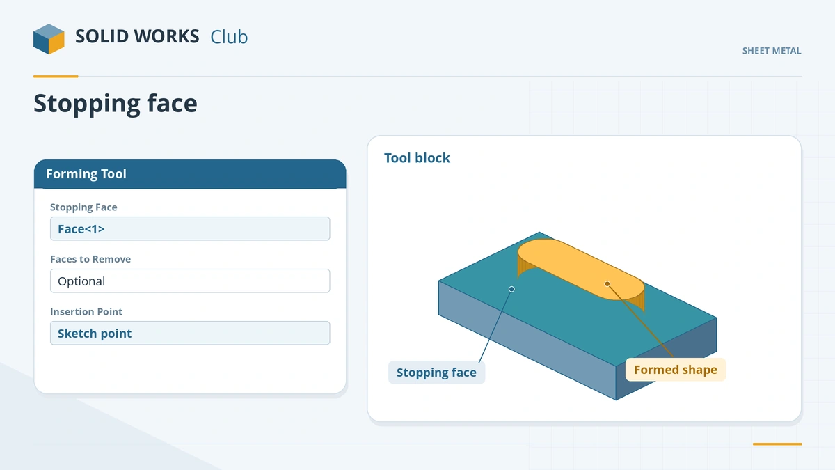
The stopping face sets the depth; faces to remove become holes. -
3
Save as a form tool
File → Save As → Form Tool (*.sldftp) into a folder the Design Library can reach.
-
4
Place it
Drag the tool from the Design Library onto the base flange's top face, set the rotation, then position it on the Position tab and click the tick.
Common mistakes
- Multibody tool parts — join the geometry into one body.
- Inside fillets smaller than the thickest sheet the tool will form — the tool can fail.
- Saving any part as .sldftp without a Forming Tool feature — no warning, but it errors when used.
- Forming downwards — forming upward avoids marking the part and bowing the sheet.
Lesson 8 of 13 in the sheet metal course.
Practice
Make the 20 × 10 × 3 emboss tool and place it on the 100 × 60 base flange. Check: the emboss stands 3 mm above the top face, and the tree shows the placed tool as one feature.
Sources
- CADimensions — How do forming tools work?
- GoEngineer — Creating custom forming tools (Jan 2017)
- GoEngineer — Forming on the edge with the Forming Tool (Nov 2018)
- Javelin — Utilizing the form tool for sheet metal parts (Oct 2025)
- Javelin — Managing formed feature information (Apr 2021)
- GoEngineer — SOLIDWORKS 2024 sheet metal updates (Nov 2023)
- Javelin — SOLIDWORKS 2024 sheet metal and fabrication (Feb 2024)
- SOLIDWORKS blog — Sheet metal tutorial PDF (Mark Eilers)
Checked November 2026. SOLID WORKS Club is independent; menu names can differ slightly between releases.
Frequently asked questions
How do I make a custom forming tool in SOLIDWORKS?
+
Model the shape on a block, add the Forming Tool feature with a stopping face (and faces to remove for holes), and save as a .sldftp form tool.
Where are forming tools stored?
+
.sldftp tools can live in any folder the Design Library reaches. Older .sldprt tools need a folder marked as a Forming Tools Folder.
How do I show forming tools in the flat pattern?
+
The form tool feature has flat pattern visibility settings, and form feature colours for flat pattern views are set in Document Properties.
What is the Stamp feature?
+
Added in SOLIDWORKS 2024, Stamp makes an indent from any closed sketch with depth, draft and radii, without a forming tool.
Related
- Flat patterns in SOLIDWORKS sheet metalHow the SOLIDWORKS flat pattern works: Flatten, Flat-Pattern options, Unfold and Fold for cuts across bends, bend lines and flat drawing views.
- SOLIDWORKS Design LibraryHow to use the SOLIDWORKS Design Library: default folders, adding your own folders, saving reusable library features (.sldlfp) and inserting them.
- Sheet metal cornersFinish SOLIDWORKS sheet metal corners: Closed Corner butt, overlap and underlap, Break Corner fillets and chamfers, Corner Relief and Welded Corner.
- Base Flange — the first sheet metal featureStart a SOLIDWORKS sheet metal part with Base Flange/Tab: open and closed profiles, thickness, bend radius, K-factor, gauge tables and auto relief.