Flow Simulation · Lesson 1
Internal and external flow — a first project
Internal analysis is flow inside walls — pipes, valves, enclosures. It needs a watertight cavity, so openings are closed with lids. External analysis is flow around a body — a wing, a car, a heat sink in open air. The wizard sets both up; boundary conditions, goals and a sensible mesh do the rest.
 Kevin Walsh
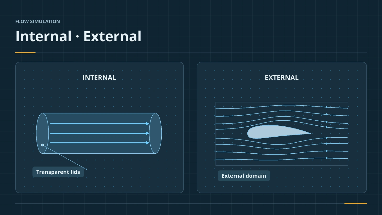
Where to find it
Tools → Add-Ins → SOLIDWORKS Flow Simulation; Flow Simulation tab → Wizard
Internal vs external
| Internal | External | |
|---|---|---|
| Flow | Inside walls | Around a body |
| Examples | Pipes, valves, enclosures | Wings, vehicles, heat sinks in air |
| Openings | Closed with lids | — |
| Domain | Encloses the fluid volume | Box around the body |
Mesh: the basic mesh fills the domain, the level of initial mesh refines it around geometry (start around level 3), local mesh controls add cells at small features, and adaptive refinement can run during the solve. A good answer is converged and mesh-independent. For solid-only heat transfer, a thermal study is lighter.
Step by step
-
1
Model a pipe and close it
Model a straight pipe, Ø50 mm inside, 500 mm long, 3 mm wall. Flow Simulation → Tools → Create Lids on both end faces.
-
2
Run the wizard
Wizard: SI units, analysis type Internal, fluid Water, default wall and initial conditions.
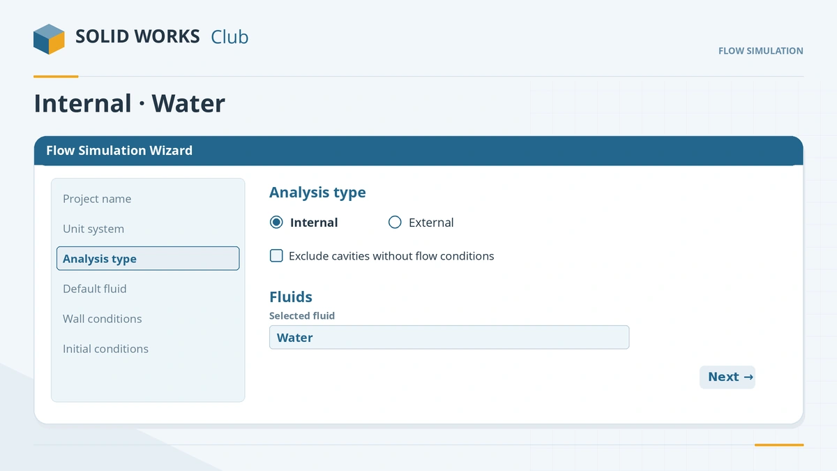
The wizard sets units, analysis type, fluid and default conditions. -
3
Boundary conditions
On the inner face of the inlet lid, an inlet volume flow of 0.001 m³/s. On the inner face of the outlet lid, an environment (ambient) pressure of about 101 kPa.
-
4
Goals, run, results
Add surface goals for average velocity at the outlet and average pressure at the inlet. Run, then make a cut plot of velocity along the pipe axis.
Common mistakes
- Boundary conditions on the outer face of a lid — use faces touching the fluid.
- A tiny gap in the model — the fluid volume is not found; use Check Geometry and Leak Tracking.
- Trusting one mesh — check that goal values stop changing as the mesh is refined.
Lesson 1 of 1 in the Flow Simulation course.
Practice
Run 0.001 m³/s of water through the Ø50 mm pipe. Check: the average outlet velocity is about 0.51 m/s — volume flow divided by area, 0.001 / (π × 0.025²) — and inlet and outlet mass flow match.
Sources
- CATI — How do I create a Flow Simulation project? (Aug 2020)
- GrabCAD — Getting started with the Flow Simulation wizard
- Engineers Rule — Flow Simulation basic concepts (May 2016)
- GoEngineer — Creating lids in Flow Simulation (Sep 2023)
- TriMech — Avoid frustrating errors in Flow Simulation (Jul 2019)
- Solid Solutions — Leak tracking in Flow Simulation (Jul 2014)
- Javelin — Solving the face-not-on-boundary error (Nov 2025)
- SOLIDWORKS Blog — Goals in Flow Simulation (Jan 2015)
- GSC — Meshing in Flow Simulation, part 1 (Jul 2015)
- GSC — Meshing in Flow Simulation, part 2 (Aug 2015)
- CATI — Mesh recommendations for Flow Simulation (Aug 2009)
- CATI — Control your flow mesh (Nov 2018)
- Solid Solutions — Finding a good mesh fast in Flow Simulation (May 2019)
- CATI — Viewing Flow results and a first cut plot (Jan 2021)
- CATI — A first Flow Simulation surface plot (Feb 2021)
- CATI — Flow Simulation trajectory plots (May 2017)
- GoEngineer — Flow Simulation recirculating system (Nov 2022)
Checked November 2026. SOLID WORKS Club is independent; menu names can differ slightly between releases.
Frequently asked questions
What is the difference between internal and external analysis?
+
Internal flow is bounded by walls, like a pipe, and needs closed openings. External flow surrounds a body, like air over a wing.
How do I close openings for an internal analysis?
+
Use Create Lids on planar faces with openings, or model lids yourself as extrudes with Merge result off for non-planar openings.
Why is my fluid volume not recognised?
+
There is a gap. Run Check Geometry and Leak Tracking, picking one face inside and one outside.
What are goals for?
+
Goals are the values you care about; with Use for Conv on (default) they decide when the solution has converged.
Related
- SOLIDWORKS Flow SimulationSOLIDWORKS Flow Simulation explained: what the CFD add-in solves, licensing, HVAC and Electronics Cooling modules, the wizard, goals, mesh and results.
- Thermal studiesRun a SOLIDWORKS Simulation thermal study: steady state vs transient, temperature, heat power, convection and radiation, thermal resistance, and thermal stress.
- SOLIDWORKS ShellHow to use Shell in SOLIDWORKS to hollow a part: faces to remove, wall thickness, shell outward, multi-thickness walls, and what to do when the shell fails.
- Meshing in SOLIDWORKS SimulationSOLIDWORKS Simulation meshing: blended curvature-based mesher, density slider, mesh controls, draft vs high quality elements, aspect ratio, convergence.